What's new
Van's Air Force

Don't miss anything! Register now for full access to the definitive RV support community.

Schottky Diode failure mode

clutch22

Well Known Member
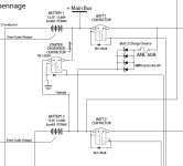
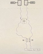
I have a set of diodes installed in my power bus system. Alt 1 charges batt 1 and alt 2 charges batt 2. A pair of shottky diode puck is installed so that the two charging systems can't backfeed into the other.

At some point in the build, my diode has failed. Maybe it was bad when I installed it, I'm not sure. During a few ground runs prior to first flight, I noticed that my power system didn't seem right, and I traced it down to the diode. I have continuity both ways (or voltage in both directions) on both diode sides.

I have a new diode on order, and in the meantime I'm wondering, when a diode fails, will it always fail in a manner that allows power to feed through it in the normal direction (i.e. the busses still receive power)?
 
Be sure to use heat conductive paste between the diode and its heatsink.
Heat is the enemy of electronics.
 
I take it from your post that you are feeding some heavy current through these diodes. If so, find diodes rated for at least twice your max current flow and use big boy heatsinks on them.

I would not use this approach as my first choice for what you want to do.

Carl
 
I have a heatsink on order with my new diode. My first wasn't installed with one, but it was mounted on aluminum angle. So, I'm not sure if that was adequate, but I ordered a sink & thermal paste with the replacement.
The diode pair is rated at 45v/60A, and my normal current draw should be less than 15A.

I'll admit that my system is not the most simple. On paper it will work great, but this failed diode has me a little nervous about them. As I'm typing this, I'm wondering if I should run a switched emergency bypass wire around the diode...
 
Welcome to the challenges of building an all electric plane that doesn't have some unexpected single point failure modes. Anyhow...

15 amps ... a typical Shottkey diode drops 0.4 volts, so we can expect it to generate 6 watts of heat... which is not insignificant. Now say for some reason (low battery) your 60 amp alternator goes full output, then we are looking at 24 watts. A common soldering iron is 25 watts. That's going to need a significant heat sink (maybe a fan too) to avoid overtemp. If you provide the diode part number I can analyze this further.

I did something similar combining two banks of batteries to an inverter for an off grid cabin, and ended up with a heat sink that was around 1 x 5 x 8 inches

My circuits classes were a long time ago, but I do play around with some off grid power circuits so all isn't forgotten!
 
Now say for some reason (low battery) your 60 amp alternator goes full output, then we are looking at 24 watts. A common soldering iron is 25 watts. That's going to need a significant heat sink (maybe a fan too) to avoid overtemp. If you provide the diode part number I can analyze this further.

My diode is the last stop before a 15 amp engine bus. It’s not between the batteries and alternator.

From Digi-key:
Diode PN: STPS12045TV
Heat sink PN: 345-1048-ND

Thanks.
 
Andrew - you need a #8 wire to feed the engine power buss? That is a lot of current draw.

Carl

Carl,
I did install #8 wire there, but it’s probably overkill IMO by the diagram designer.
It is an SDS system and that is all that is on this bus. SDS states their system draws 12-14 Amps.
 
Carl,
I did install #8 wire there, but it’s probably overkill IMO by the diagram designer.
It is an SDS system and that is all that is on this bus. SDS states their system draws 12-14 Amps.

Making some assumptions here but there's probably some decent margin there for wire size chosen. Guessing the coils have a significant but very short lived high current flow during their initial charge. This is only a guess.
 
alternate diode test method

... power system didn't seem right, and I traced it down to the diode. I have continuity both ways...

Both ends were disconnected when tested...

If your ohmmeter is set to megohms It could be looking at reverse leakage and giving you a false impression.

You might test the diodes with a small lamp and battery or measure the voltage drop with a load applied, like the ECUs, looks like they are always on when the engine bus is hot.

What are the symptoms of "didn't seem right"?
.
 
What are the symptoms of "didn't seem right"?
.
The system design is:
Alt #1 charges Batt #1
Alt #2 charges Batt #2

But:
Alternator #1 was charging battery #2 when the #2 alternator was offline. In this design, they are to be completely isolated from each other unless the buss-tie contactor is closed.
 
Last edited:
Andrew, two lithium iron batteries?

Break.

Question for the group. Consider two Odyssey AGM batteries connected to the same alternator in parallel. Assume one is at a low state of charge and the other is near full charge. Disconnect the discharged battery and we can expect a momentary voltage rise, but we typically assume the fully charged battery will absorb the spike. The lead acid battery acts like a shock absorber or accumulator, and the charge rate into the discharged battery was relatively low.

Now consider two lithium iron batteries charged in parallel. Same scenario. If we suddenly disconnect the discharged LiFePO4, will its fully charged partner absorb the spike? Note the spike will be larger even if the fully charged battery accepts some of the surge, as the charge rate into the lithium battery was far higher.

Consider Andrew's crossfeed contactor and you'll see where I'm going here.
 
Last edited:
I have seen in the past that diodes typically fail as a short, but not always and sometimes fail as an open. On circuit boards this often results in them taking other components with them. In your application the result is loss of the isolation you were planning. The problem with these types of failures is you may not realize that the diode has failed.
 
Consider Andrew's crossfeed contactor and you'll see where I'm going here.

Dan,
Can you please elaborate for me?
I’m pretty decent at following schematics, but I don’t necessarily know the micro-details behind the scenes.

Also, this plane is 100% finished, ready for first flight. My new diode pair is arriving tomorrow and will be a quick install. Are you seeing something critical that needs changed prior to flight?
 
Bus tie

The system design is:
Alt #1 charges Batt #1
Alt #2 charges Batt #2

But:
Alternator #1 was charging battery #2 when the #2 alternator was offline. In this design, they are to be completely isolated from each other unless the buss-tie contactor is closed.

I thought typically bus ties use 3 diodes? 2 extra to supply power from each bus.

Here is one with 2 diodes, as the contactor comes with internal suppression.

Screenshot 2023-08-28 152933.jpg
 

Attachments

  • Screenshot 2023-08-28 154148.jpg
    Screenshot 2023-08-28 154148.jpg
    10.6 KB · Views: 36
Last edited:
My design is attached. I used four diodes to increase spike current limits (600 amps) and increase the ability to dissipate any heat that is generated. Heat is what kills diodes (and overcurrent). All told my system can handle 128 amps continuous, more than double my 60A alternators output. Additionally there is an ANL fuse and 60A breaker.

In regards to Dan's comment, my personal requirement is to not fly if either battery is not fully charged.
 

Attachments

  • Battery.jpg
    Battery.jpg
    92.4 KB · Views: 62
My design is attached. I used four diodes to increase spike current limits (600 amps) and increase the ability to dissipate any heat that is generated. Heat is what kills diodes (and overcurrent). All told my system can handle 128 amps continuous, more than double my 60A alternators output. Additionally there is an ANL fuse and 60A breaker.

In regards to Dan's comment, my personal requirement is to not fly if either battery is not fully charged.

I suspect that if Bat 2 ever ran down you would smoke those baby charge diodes.
Diodes tend not to play well with others, the one with the lowest resistance will try to carry all the load.
 
Last edited:
...

I have a new diode on order, and in the meantime I'm wondering, when a diode fails, will it always fail in a manner that allows power to feed through it in the normal direction (i.e. the busses still receive power)?

In my mind rectifier diodes typically fails open and zener diodes short.
But that experience is 4 decades old and does not include shottky diodes.

Finn
 
I suspect that if Bat 2 every ran down you would smoke those baby charge diodes.
Diodes tend not to play well with others, the one with the lowest resistance will try to carry all the load.

Batt2 is for my Essential bus and only gets used for periodically testing and for engine start (cross-feed during startup). I'm can't think of an scenario where Batt2 would run down and then a large charge would suddenly be sent to Batt2.

The highest alternator draw I have seen is 26 amps of current draw, which is still within limits for a single baby diode. But large or multiple smaller diodes, everyone can pick their poison.
 
diodes in parallel are not additive to current capacity

My understanding is the same as Walt's.

My notes are here. (Appended with the diode load sharing application note mentioned in post 31)

And the diodes in the SOT-227B case, like the one used by the OP, are electrically isolated from the mounting surface. (The OP's image seems to read diode PN DSS2X6J-0045A but I think it is actually DSS2x61-0045A)
.
 
Last edited:
And the diodes in the SOT-227B (minibloc) case, like the one used by the OP, are electrically isolated from the mounting surface.

John, can you expand on this? What do you mean? Are you saying that applying thermal paste to the mounting surface won't significantly help dissipate heat, or were you saying something else?

Thanks
 
Definitely valid criticism. Again, pick your poison.

With my design the diodes have a very tight Vf with an effective forward resistance of 0.035 to 0.039 ohms (min/max at max current) additionally all four are thermally bonded to each other via a shared heat sink. If you choose to use a single diode, my recommendation would be for a very large finned heatsink as there will be significant heat to dissipate when charge current is high.

Here is an Application note on current sharing in parallel diodes: https://www.st.com/resource/en/appl...ing-in-parallel-diodes-stmicroelectronics.pdf


My understanding is the same as Walt's.

My notes are here.

And the diodes in the SOT-227B (minibloc) case, like the one used by the OP, are electrically isolated from the mounting surface.
.
 
John, can you expand on this? What do you mean? Are you saying that applying thermal paste to the mounting surface won't significantly help dissipate heat, or were you saying something else?

Thanks

Electrically isolated, not thermally isolated.

DSS2x61-0045A is in an SOT-227B case:
  • The diodes in the case are electrically isolated from the metal mounting surface of the case.
  • The diodes are not thermally isolated from the metal surface of the case. The data sheet lists the maximum thermal resistance between the diodes and the case and the typical thermal resistance between the case and a heat sink.
  • The metal mounting surface of the case is intended to be pressed against a heat sink surface with thermal grease between; mounting holes in the case are for screws to attach the case to a heat sink.
  • AFAIK Schottky diodes in the SOT-227B are relatively newly available, like in the last ten years. Previous to that, Bob Nuckolls and others were coming up with electrical isolation schemes.

Other device cases I've noticed one side of the diode junction is electrically connected to the metal of the case so the device has to be somehow electrically isolated from the heat sink or the heat sink has to be electrically isolated from the airframe.

BTW my calculations indicate the DSS2x61-0045a is good for 30A on the firewall with a 401K heat sink which is my use case. (It's for a four-cylinder SDS injection engine bus. I placard the engine bus as 30A max so I can add other essential items to it.)
.
 
Last edited:
Batt2 is for my Essential bus and only gets used for periodically testing and for engine start (cross-feed during startup). I'm can't think of an scenario where Batt2 would run down and then a large charge would suddenly be sent to Batt2.

The highest alternator draw I have seen is 26 amps of current draw, which is still within limits for a single baby diode. But large or multiple smaller diodes, everyone can pick their poison.

Are you measuring alt output or bus load?
Not sure of your exact layout but if you’re using an EX for starting it will demand a very high initial charge current (limit of alt) until it’s topped off.
That’s a parameter I don’t like with EX, very demanding of the alternator, max output after every start/discharge.
 
Last edited:
The alternators do not charge the batteries through those diodes. There is no high current load to cause the initial failure. Too lazy to look it up right now, but the SDS stuff is probably ballpark 15~17 amps with both pumps running.

The initial failure was probably due to whacking diode 2 (see the illustration) with more reverse voltage than the rated 45V...which is why I was asking for opinions about the ability of a fully charged LiFePO battery to soak up a spike.

For now I'll go with the idea that a fully charged lithium does not serve as a very good electrical shock absorber.

Assume Battery 1 is near full charge, and battery 2 is moderately depleted. Further assume Alternator 1 is active, Alt 2 is off line, and the crossfeed contactor is closed.

Ok, crank it up. The low resistance of a LiFePO battery means initial charge rate is very high, and in this scenario it is Batt 2 being charged, through the crossfeed.

Now open the crossfeed. Unless Batt1 absorbs it, the result is a big voltage spike. I've attached a list of common transients below. Note line 3.

Assume a 100V reverse voltage transient at diode 2. It burns through D2, shorting closed. Now the charge current can pass through D1, and maybe it fries.

I'm spitballin', but it's a fair explanation for the presented problem.
 

Attachments

  • Load Dump.jpg
    Load Dump.jpg
    42.9 KB · Views: 50
  • Typical Automotive Transients.jpg
    Typical Automotive Transients.jpg
    70.6 KB · Views: 63
Last edited:
Dan,
That very well could've been what happened. Thanks for the explanation.

In your scenario, could we say then that it would be good practice that once the cross-feed is closed, it stay closed for the remainder of the flight, or at least until the batteries are fully charged? That would prevent a large voltage spike, right?
 
What is the purpose of having the cross feed contactor?

Mike,
In my case there are a few situations where you could close it:

Battery 1 is the only batt connected to the starter. Closing cross-feed would allow starting the engine with #2 battery. (I'm not saying this is a smart idea, but it allows it).

Dan edited it out of his attachment, but if you look at my original sketch, I have a VP-X which runs all my avionics. Battery 1 is connected to it. Closing the cross-feed allows Battery 2 to power the avionics.

If either alternator were to fail, the remaining on-line alternator could charge the other battery.

Or, if a Battery were to fail or throw a "fault" CAS message, you could close the cross-feed and then kill the affected master battery switch.
 
What is the purpose of having the cross feed contactor?

Chris can probably better answer this better but it appears he can use the cross feed to use both batteries together for a start and maybe more important since he is using separated busses his diodes allow the primary to feed the essential but there is no way for the essential to feed the primary. With modern pad mounted alternators with a little load shedding the back-ups can power both busses in the event the primary alternator takes a dump. (It will)
 
Dan,
That very well could've been what happened. Thanks for the explanation.

Maybe. Right now it's just a theory. Set up a test and look at the amplitude of the spike.

In your scenario, could we say then that it would be good practice that once the cross-feed is closed, it stay closed for the remainder of the flight, or at least until the batteries are fully charged? That would prevent a large voltage spike, right?

Yes, assuming I'm right about the scenario. Or add a TVS to clip the spike, or redesign the system, or install AGM batteries.
 
Battery 1 is the only batt connected to the starter. Closing cross-feed would allow starting the engine with #2 battery. (I'm not saying this is a smart idea, but it allows it).

Closing the cross-feed allows Battery 2 to power the avionics.

If either alternator were to fail, the remaining on-line alternator could charge the other battery.

Kinda what I suspected but wanted to confirm.

I had the same in the RV 10 and for the same reasons.

Never had to use it.

New plane has almost exactly same dual/dual setup but I decided against the cross feed this time. As with the 10, the Schottky diode feeds power across the system as needed to keep the fan turning.

May I suggest if you grind down the battery that you do not just simply engage the cross feed and continue trying to start. First find out why it did not start, correct that, then start on the second battery.

Take care, fly safe.

Mike
 
Last edited:
Practical question for the EE's here...

How could a user like Andrew easily measure load dump voltage? Be specific please.

I hate to bring up unproven things that go bump in the night, but it does need a look. My impression is that load dump voltage peak is proportional to alternator output current at the time of battery disconnection. The community is switching to LiFePO, and as we've seen, the initial charge rate is very high, so potentially so is the spike if a discharged battery is suddenly taken out of the circuit. The current standard requires components to withstand 60V for 100ms. Here it appears (caution, unproven) Andrew burned through a 45V diode.

Anyone have information?
 
On my design the crossfeed is only used during engine start and was intended to reduce the current draw from the primary battery. As a secondary affect, it keeps the batteries in balance with each other.

You are correct, there is no way for the essential bus to power the main bus and that my pad mounted backup alternator can fully carry the main bus load if my primary alternator dies.


Chris can probably better answer this better but it appears he can use the cross feed to use both batteries together for a start and maybe more important since he is using separated busses his diodes allow the primary to feed the essential but there is no way for the essential to feed the primary. With modern pad mounted alternators with a little load shedding the back-ups can power both busses in the event the primary alternator takes a dump. (It will)
 
Very interesting hypnosis. Some DMM meters have the "max" feature, he could set the meter up with the voltage selected to the highest level and clip the lead to the diode (engine power bus side).

Practical question for the EE's here...

How could a user like Andrew easily measure load dump voltage? Be specific please.

I hate to bring up unproven things that go bump in the night, but it does need a look. My impression is that load dump voltage peak is proportional to alternator output current at the time of battery disconnection. The community is switching to LiFePO, and as we've seen, the initial charge rate is very high, so potentially so is the spike if a discharged battery is suddenly taken out of the circuit. The current standard requires components to withstand 60V for 100ms. Here it appears (caution, unproven) Andrew burned through a 45V diode.

Anyone have information?
 
The first thing I might try would be a simple peak detector circuit using suitably rated components. Hook your DMM to it, initiate the event, and read the measured voltage immediately after.
 
Practical question for the EE's here...

How could a user like Andrew easily measure load dump voltage? Be specific please.

Anyone have information?

Borrow an oscilloscope, or buy one of the super-cheap DAQ/Scope USB devices and use a voltage divider to keep it in range of the input. Here's one for example for $40 (disclaimer - I have not used this one but there are similar devices out there):
https://www.amazon.com/EspoTek-Labr...ywords=usb+oscilloscope&qid=1693363947&sr=8-4

If you use a line powered scope, pay attention to ground potential differences between the scope and the airplane.

I have dual-ETX batteries in my design so I'm interested in the results of a load dump event.

-Bob
 
Last edited:
Instead of trying to measure load dump voltage (which would vary based on battery charge level, downstream accessory load, etc), just install one or more TVS diodes as Dan alluded to earlier. Use automotive-grade units specifically designed for this purpose.

Modern cars have TVS diodes built into the alternator, but with the ancient Denso-design alternators we use (40 years old now), I doubt any of them have that protection. Yeah, we have crowbars thanks to Nuckolls et al, but those don't do anything to suppress load dumps.

Here's some light reading on the subject:

https://m.littelfuse.com/~/media/el...utomotive_tvs_diodes_application_note.pdf.pdf
https://www.littelfuse.com/~/media/...es/littelfuse_tvs_diode_sld_datasheet.pdf.pdf
https://www.diodes.com/assets/App-Note-Files/TVS-in-Automotive-Applications.pdf

The SR22 has TVS diodes all over its electrical system (for lightning protection) and I was going to add some to my design to handle transients/load dump issues until I read about a bunch of failures that caused smoke in the cockpit:
http://servicecenters.cirrusdesign....ies/2007ServiceAdvisories/SA07-17/SA07-17.pdf
https://ad.easa.europa.eu/blob/CE0812R1.pdf/SIB_CE-08-12R1_1
http://servicecenters.cirrusdesign.com/tech_pubs/SR2X/pdf/SB/SR2XBulletins/SB2X-24-09/SB2X-24-09.pdf
It was probably just a bad batch but the fix was to add inline fuses to protect against a failed shorted TVS. I could be persuaded to add them back to my design (with a series fuse) if I had data that showed they were needed. But if they're not needed, that's one less component to fail.

-Bob
 
So, anyone with dual LiFePO's and a crossfeed contactor want to do the check for spike voltage?

Something punched through those diodes...
 

Attachments

  • Transients.jpg
    Transients.jpg
    53.8 KB · Views: 48
Last edited:
So, if you wanted to use TVS as insurance for a dual EarthX system feeding a bus through diodes, what is the best place to put them? On the EarthX batterys' positive leads? Downstream of the battery contactors?
 
So, if you wanted to use TVS as insurance for a dual EarthX system feeding a bus through diodes, what is the best place to put them? On the EarthX batterys' positive leads? Downstream of the battery contactors?

The Cirrus example below. Without measurement, we don't know if they are actually needed.
 

Attachments

  • SR22.jpg
    SR22.jpg
    285.4 KB · Views: 55
Back
Top