What's new
Van's Air Force

Don't miss anything! Register now for full access to the definitive RV support community.

RV A model nose gear idea

Allan...

Re the data, I can assure you there is a lot of interest in the UK already for your brace. However, the fitting of it is not solely up to the owner - the "modification" must be applied for, then approved, by the "LAA", before it can be flown.

They will require some engineering data / justification / compliance with standards. Even your video would go someway to providing that... although as ever, it then asks more questions (as you are seeing here).

I am not suggesting "all" your data is required, but I am sure it will help the eventual market if, when you can, some data is collated and released. Ideal would be for you to liaise with a UK RV owner to smooth the process i.e. let the owner do the battle with the LAA, but you assist that owner with their requirements - assuming they are "reasonable" in scope.

Won't be me I'm afraid, our 3rd wheel is at the back, but I suspect you will be contacted soon, if not already.

Andy
 
Nose Job

Bottom Line: Motor mount... Who Cares!, Bent Prop.... Who Cares!, Up Right Wreckage I can walk away from..... Priceless!
 
Thanks for designing and manufacturing something that will add to the safety of our community.
One question---It appears from what I've read that the nose gear rod fairing is included. Assumption is that this fairing is larger to accommodate the brace. Does the upper intersection fairing between the provided fairing and the cowling have to be modified to fit the larger fairing??
 
Light Aircraft Association

Hi Alan,

You have probably noted my response to your innovation....... I think its the best solution to the nosegear 'problem' devised to date. As noted above there will be considerable interest in this in the UK, where we are governed by the LAA.

Francis Donaldson the the Chief Engineer and his team who do all the approval work are very clever people and also very pragmatic. My guess is that their concerns would be:-

1. The failure mode of the gear leg with it fitted. However, as it is designed to prevent the flip over at lower speeds, and failure with it at higher speeds would require much more inertia to cause the gear to fail higher, or at the mount...... a catastophe would have happened anyway, so perhaps this can be argued to be a mute point.

2. Wear on the gear leg caused by normal operation, or out of predominately rough fields.......... will this cause wear ridges in the upper/ lower sections of the gear where it could contact in these circumstances. I suspect a regime of checking for such wear would be sufficient here.

3. Cracking or bending of the engine mount ........ again visual inspection and dye penetrant tests should make sure all is well here.

4. The centre clamp may cause corrosion in the gear leg if not properly protected.......... I assume the parts will be plated to prevent this.

So, as I am likely to be one of your first Uk customers I will speak to LAA engineering today to establish if my thoughts are correct. If someone else has already taken this up I will let you know.
 
Thanks for designing and manufacturing something that will add to the safety of our community.
One question---It appears from what I've read that the nose gear rod fairing is included. Assumption is that this fairing is larger to accommodate the brace. Does the upper intersection fairing between the provided fairing and the cowling have to be modified to fit the larger fairing??

No! the fairing is exactly as original and plugs right in. Thanks, Allan
 
UK LAA

Hi Andy

Well I am surprised no one has apparently contacted the LAA on this yet. Does your website ave drawings I can download and submit on a mod application.

I will do this on what we call a standard mod for all nose gear types, when this goes through it will open the door for all Uk builders owners to use it.
 
What Steve is asking....

concerns would be:-

1. The failure mode of the gear leg with it fitted. However, as it is designed to prevent the flip over at lower speeds, and failure with it at higher speeds would require much more inertia to cause the gear to fail higher, or at the mount...... a catastophe would have happened anyway, so perhaps this can be argued to be a mute point.

2. Wear on the gear leg caused by normal operation, or out of predominately rough fields.......... will this cause wear ridges in the upper/ lower sections of the gear where it could contact in these circumstances. I suspect a regime of checking for such wear would be sufficient here.

3. Cracking or bending of the engine mount ........ again visual inspection and dye penetrant tests should make sure all is well here.

4. The centre clamp may cause corrosion in the gear leg if not properly protected.......... I assume the parts will be plated to prevent this.

This is what I unsuccessfully tried to ask in my earlier post. I was misunderstood as being negative on this product.

Let me state that I have no reason to doubt that this product works as the designer claims.

If I ever decide to use my plane on rough fields, I may well buy one myself.

But I still want to know the down side of doing this modification to my plane.

There will be a trade off and I want to know what they are.

1. A small amount of addition weight up front.
2. Increased inspection responsibility?
3. ???

I am not going to list the benefits as they have already been stated many times, so please don't respond to this post listing all the good things about this product. I want to know about the downside which haven't been addressed.

Kent
 
Re: What Steve is asking....

This just may be a case where any downsides show up as a lot of these are installed in the field and get a lot of hours on the mod.

This mod could help even if you dont normally land on rough fields.

I remember the one RV that had the nosewheel bend over from just landing on the runway and the RV hit a bump where two runways intersected?

Another one was at Oshkosh in 2008 when a RV taxied into the Homebuilt camping area and hit something and bent his nose gearleg like a pretzel.

I suspect that both of these incidents could have prevented a prop strike with this mod?
Actually, I was not sure why my request was taken so offensively. I was wanting to see some test data that may show specifics on where the bending/breaking/etc. failure occurs with or without the brace (i.e. with the brace the bending force is greatest at xxx inches from the motor mount; without the brace the bending force is greatest at yyy inches from the motor mount).

Allan, I was no way asking for all of your RAW data. My apologies if that is what was inferred from my request. I am one of the many who has already put my name in the queue to purchase one. I am convinced already. I just would like to see some more information if it is available. In fact, I would really like to see video that showed the permanent bending/breaking point of a non-braced gear leg when you were testing, assuming you were videoing those tests.

Sorry for causing heartburn with that request.
 
Pic of broken nose gear

I can post a pic of a broken nose gear leg. It appears to have snapped cleanly after bending.

p1020418b.jpg
 
Last edited:
I can post a pic of a broken nose gear leg. It appears to have snapped cleanly after bending.

p1020418b.jpg
Wow? was there any type of stiffener installed on this gear leg? Is it the older type when it is not tapered in the middle?
It seems so uncharacteristic of the typical bend which takes place closer to the wheel and where it is weakest.
 
Downsise

Hi Kent,

Please don't take any of my post as suggesting there is a downside to this product............ there may be none other than a bit of nose weight and a few more things to inspect.

These are merely things I consider it prudent to ask about and which I suspect LAA will ask about. Although if I lived in the states and did not require approval they are certainly things I would check on a regular basis.

The one potential flaw I can see with the design is that if there was contact between the upper and lower point of the stiffener in normal operation, or predominant rough field work, then the gear leg could be weakened at both the upper and lower contact points......... which could lead to a premature failure of the leg if not spotted.

However, I believe that Allan has probably engineered this potential problem away so it may not even exist as a problem.......... if that makes sense.

Bottom line is that I still think this is a very good idea, looks well engineered and thought out. As I say I will probably be the first UK buyer.
 
Hi Kent,

The one potential flaw I can see with the design is that if there was contact between the upper and lower point of the stiffener in normal operation, or predominant rough field work, then the gear leg could be weakened at both the upper and lower contact points......... which could lead to a premature failure of the leg if not spotted.

However, I believe that Allan has probably engineered this potential problem away so it may not even exist as a problem.......... if that makes sense.

Bottom line is that I still think this is a very good idea, looks well engineered and thought out. As I say I will probably be the first UK buyer.

The brace in any kind of normal operation will never ever come in contact with the gear leg. It only touches when the gear is under possible destructive stress. It is like an air bag, it will never touch your face unless you crash. Thanks, Allan Anti Splat Aero LLC
 
I can post a pic of a broken nose gear leg. It appears to have snapped cleanly after bending.

p1020418b.jpg

Thanks for posting this as I have only seen one other that actually broke in half. The "Nose Job" would have prevented this one for sure.
Allan Anti Splat Aero
 
Nose Gear Data

Not sure why my previous posts were taken in a negative way either. Perhaps because of "engineer speak" a kind of shorthand that engineers use to try to get to the heart of the issue quickly.

So let me state again that I think this is a great idea and that the design and testing that have gone into it just by viewing the videos are very impressive.

Some comments to the inventor regarding issues raised by other posters about inspection/corrosion/contact issues. You may want to consider urethane bumpers at each end of the brace to keep the powder coating intact during contact. Also consider a urethane sleeve between the clamp and the gear leg for the same reason.

No I didn't ask Vans for a report on their gearlegs or main spars or flutter testing. I watched Van perform low level show aerobatics enough times to have confidence in the integrity of the airframe. In addition, from previous issues of the late lamented RVator (no their Facebook does not perform the same function) I was aware of the static load testing, the ground vibration/flutter tests, the gear drop tests and the nose gear cycling machine. I was quite satisfied until I started hearing about pogo stick flips on the -A models.

Back to the gear leg brace. I was confused by the reference in the testing video about the load moving forward to the front of the contact patch, so I would like some clarification of the loads that were used for the design analysis and tests. No I don't want to see your RAW data, and neither did a previous poster. So if you can say that the vertical static load on the nosewheel is X, and the overload vertical load is some multiple of X, and that a horizontal load of some fraction of the overload vertical load was applied at the axle centerline, and the leg with the brace could withstand this load, then I would be quite happy and would consider one for my RV-9A.
 
Hi Alan,

You have probably noted my response to your innovation....... I think its the best solution to the nose gear 'problem' devised to date. As noted above there will be considerable interest in this in the UK, where we are governed by the LAA.


4. The centre clamp may cause corrosion in the gear leg if not properly protected.......... I assume the parts will be plated to prevent this.

So, as I am likely to be one of your first Uk customers I will speak to LAA engineering today to establish if my thoughts are correct. If someone else has already taken this up I will let you know.

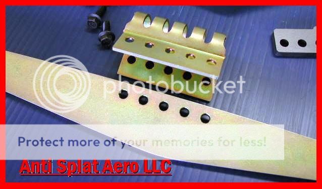
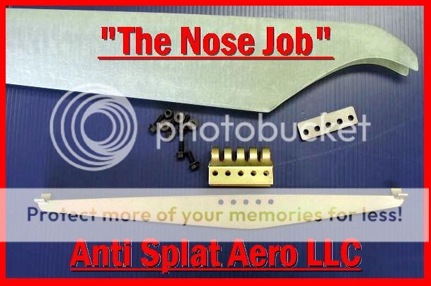
We have made an improvement in the package on this next run that is in process as we speak. No more powder coating the parts. the powder coating was actually mushing out where the clamp was squeezing the brace. We now are Gold cad plating the brace and clamp. This will also eliminate any chance of corrosion between parts. Anyone who would like to send back their powder coated parts from the first run for the plated ones (used or not) is more than welcome to do so at no charge and We will pay freight both directions. Thanks for the question. Allan Anti Splat Aero LLC

EPSN0002-1.jpg


EPSN0001.jpg
 
Last edited:
It's from circa 1997.

Wow? was there any type of stiffener installed on this gear leg? Is it the older type when it is not tapered in the middle?
It seems so uncharacteristic of the typical bend which takes place closer to the wheel and where it is weakest.
 
New Avitar for Anti Splat Aero

We decided to change our avatar to a more appropriate one for the new product line. This was a tremendous undertaking for me with my lack of computer graphic skills, so please let me know what you guys think. Regards, Allan
 
Not an official response from Van's Aircraft, this is just a personal observation provided as food for thought.
I have no opinion one way or the other whether installing one of these devices is a good thing... That is something "A" model fliers will have to decide on their own. The reason I am bothering to post in this thread though, is in the hope that people will look at the complete picture when making that decision.

The only discussion I have seen is regarding physical/mechanical aspects of this type of modification.

It may come as a surprise, but it is possible that it will induce some aerodynamic ones as well. I am not meaning to imply that I know it will, but that is why we test changes.... to verify whether they do have an effect or not.

It has been mentioned that the standard nose gear leg fairing can not be used and that a different one is provided. In the posted photo it looks like it is definitely wider in cord than the standard fairing (at least on the most fwd portion, which would be the least desirable portion as explained below).

The reason this "could" (not saying it will, would have to do some testing) be an issue, is because any vertical member fwd of the C.G. has a negative effect on yaw stability and spin recovery. It basically negates some of the effect of the vertical stab. and rudder. The larger the surface area, and/or the further fwd of the yaw axis (C.G.) that it is, the more critical it could be.
In the past there has been concern for some of the after market gear leg fairings builders were using on tail dragger RV's. The tail draggers main gear legs are fwd of the yaw axis and the fairings are enough larger that it might have some aerodynamic effect on spin recovery, etc. I am not aware of any of those suppliers doing additional spin testing, so cant' say whether they do or not.

Vans provided rudder upgrades to any RV-7 builders who wished to have enhanced spin recovery (and as far as I am aware, all RV-7 builders used the larger rudder). Installing a larger nose gear leg fairing, without consideration for the aerodynamics effects could be canceling out (at least some of) the benefit gained by using the larger rudder, as well as reducing the yaw stability and/or spin recovery on other tri-gear models.

I am not meaning this as a scare tactic. I have no way of knowing what the effects might be. I have no information regarding how much of a surface area increase the new fairing has... It might have no measurable effect at all. But if I have learned one thing in the 18+ years I have been involved with these airplanes, it is that I have been surprised by test results far more times than I would ever have imagined

Thank You Scott........ for taking the time to explain this issue. I set it out there in this post...... http://www.vansairforce.com/community/showpost.php?p=584647&postcount=54 but as you can see it was never questioned.
 
Not an official response from Van's Aircraft, this is just a personal observation provided as food for thought.
I have no opinion one way or the other whether installing one of these devices is a good thing... That is something "A" model fliers will have to decide on their own. The reason I am bothering to post in this thread though, is in the hope that people will look at the complete picture when making that decision.

The only discussion I have seen is regarding physical/mechanical aspects of this type of modification.

It may come as a surprise, but it is possible that it will induce some aerodynamic ones as well. I am not meaning to imply that I know it will, but that is why we test changes.... to verify whether they do have an effect or not.

It has been mentioned that the standard nose gear leg fairing can not be used and that a different one is provided. In the posted photo it looks like it is definitely wider in cord than the standard fairing (at least on the most fwd portion, which would be the least desirable portion as explained below).

The reason this "could" (not saying it will, would have to do some testing) be an issue, is because any vertical member fwd of the C.G. has a negative effect on yaw stability and spin recovery. It basically negates some of the effect of the vertical stab. and rudder. The larger the surface area, and/or the further fwd of the yaw axis (C.G.) that it is, the more critical it could be.
In the past there has been concern for some of the after market gear leg fairings builders were using on tail dragger RV's. The tail draggers main gear legs are fwd of the yaw axis and the fairings are enough larger that it might have some aerodynamic effect on spin recovery, etc. I am not aware of any of those suppliers doing additional spin testing, so cant' say whether they do or not.

Vans provided rudder upgrades to any RV-7 builders who wished to have enhanced spin recovery (and as far as I am aware, all RV-7 builders used the larger rudder). Installing a larger nose gear leg fairing, without consideration for the aerodynamics effects could be canceling out (at least some of) the benefit gained by using the larger rudder, as well as reducing the yaw stability and/or spin recovery on other tri-gear models.

I am not meaning this as a scare tactic. I have no way of knowing what the effects might be. I have no information regarding how much of a surface area increase the new fairing has... It might have no measurable effect at all. But if I have learned one thing in the 18+ years I have been involved with these airplanes, it is that I have been surprised by test results far more times than I would ever have imagined

I am pleased and understand fully the position you have taken in regards to our new safety product. As we neared the final stages of design and testing of this product and realized that a new fairing was necessary. We made an attempt at addressing these concerns (tho not the most scientific). The new fairing adds 9.4 sq. inches of side profile and no added frontal area.The real world testing that was done, we used my RV-9A and an RV-7A belonging to a long time associate and very accomplished aerobatic pilot. He owns a Pitts S2 and an Extra-300, The RV-7A is actually his wife's pride and joy. I have addressed with my plane the yaw issue to some extent, as it has always had a bit more yaw than I think is desirable. It has always performed flawlessly in smooth air but has a tendency to dance around the yaw axes in rough air. I actually have built an electronic yaw control and rudder trim system that is still in beta stage but works flawlessly so far. I fly quite a lot and have logged over 200 hr. this year in my 9-A alone so I am very sensitive to the subtlest of change in feel or performance. I tried to test yaw with no fairing, stock fairing, new fairing, with and without wheel pant to find no difference in feel or sensitivity adjustment required to cancel off the self induced yaw. I concluded from this, the new fairing has no or at most a miniscule effect on yaw or rudder trim. Alfred then duplicated the test sequence on his 7-A performing several spins in both right and left directions with no fairing, stock and new fairings. He concluded, were there any difference it was undetectable. We realize that this isn't the most sophisticated of tests but was all we have reasonable access to. If you could or will do further testing i will send you a complete assembly for evaluation. We were trying to add a small safety net without effecting the function or performance of the gear leg as designed. We realize the work and engineering that went into the stock gear leg and feel it is great the way it is supplied from vans. What ever margin of safety our products provide can only help and benefit the entire flying community. The last thing we would want to do is place on the market a product that had any potential of causing harm or property damage. Again, thank you for stating your position and concerns as to this product I sincerely hope we can follow up with your evaluation but fully understand your position. Regards,Allan
 
Last edited:
Are there any plans for testing with a 6A? I think this would be a valuable exercise considering the smaller vertical stabilizer and rudder surface compared to the 9 and 7. I am very encouraged by what I have seen so far!
 
Allan, I haven't ready every post, but did search on advertiser and price, and checked the list of advertisers. Have you and DR reached the point where you are an advertiser on this forum? If so, do you have your pricing established? I'm looking to build an -?A, and, being an engineer, your design makes sense to me, so I'd likely be adding this to whatever I build. Just would like to know where things stand on advertising, price, and availability.
 
Allan, I haven't ready every post, but did search on advertiser and price, and checked the list of advertisers. Have you and DR reached the point where you are an advertiser on this forum? If so, do you have your pricing established? I'm looking to build an -?A, and, being an engineer, your design makes sense to me, so I'd likely be adding this to whatever I build. Just would like to know where things stand on advertising, price, and availability.

Thanks for the vote of confidence. We have the forums mix up taken care of and are currently marketing our products. We are in our second production run of 400 kits and most of them are sold already. The kits are available at $379.00 plus freight of $14.00 to lower 48 states. Our web site is AntiSplatAero.com and e-mail is [email protected]. Keep your eyes open as we are releasing new products regularly. Thanks, Allan Anti-Splat-Aero LLC
 
Any thoughts to Nose tire pressure?

Hello everyone. I have been watching this topic for several weeks and although I wasn't able to view the videos until a few days ago, I am very interested in this product.
After watching the videos and reading other post concerning tire pressure, I was hoping some engineers, or anyone smarter than me can chime in here.

1) There are several post on recommended tire pressures and what guys are running. Most, on the nose wheel are between 30-40psi. Higher psi and guys are reporting nose shimmy. So my question is that in the video Allen talks about using 50psi 'recommended' as it produces less contact between the suface and the tire, while raising the nose fork higher. This also increases the angle of interference from obstacles to more vertical vice horizontal. Doing this also subjects you to more shimmy potential. Those of you who have installed the brace, have you increased the psi you are running or kept it the same?

2) Probably a question for Allen, but if you are recommending 50psi, and I understand why, has there been any testing at lower psi that guys may be running? Lower psi will increase the area of contact between the tire and surface, lower the nose fork and increase the angular component horizontally associated with uneven surfaces. I.e. if you hit a pot hole with a 50psi tire, the angular component is 'X' degrees of force (this is represented by the jack applying pressure in the demo videos). If the same pot hole is hit with a 30-35psi tire, the angular 'degree' component will be less 'x' in terms of degrees, but will put a greater force on the nose gear because of the greater horizontal force component, call it 'Y'. What would be the difference in X and Y?

I hope I haven't went too geek on this, if so, let me know and I will put away my protractor!

Thanks,

Dan Thompson
 
I've always run 40-50 psi and don't have a shimmy problem. If you have a shimmy than look for other causes like balance, tire out of round, bad conical washers or loose setting on the break out force.
 
Thanks Walt

Thanks Walt. I do not have a shimmy problem, but was just curious if others were increasing their pressure to the recommended pressure.

Also, was wondering what the engineers thought of running less psi in the nose wheel. I think it makes it more susceptible to nose gear problems, thus validating the 'Nose Doctor' even more!

Thanks for the reply.

Dan
 
SURPRISED!!!!!!!!!!!!

...We recently attended some very good aviation events one being the rather large Chino Ca. airshow. The RV turn out was very large at this venue. I made a point to speak with as many of the RV owners as I could in an attempt to promote our products. To my dismay, I found that only about one third of them use or for that matter are even aware of this forum. I would never have thought or believed those numbers had I not seen for myself. I can't imagine building or owning an RV and not using this great resource. I wish I could obtain an E-Mail list of all the RV owners, Wow! what I would be willing to pay for that one? We could acquaint them all with the VAF forums and intern promote our products and services as well. Regards all, Allan...:D
 
Last edited:
installed

I installed the 3-way nose job: brace, wheel bearing, lip skid. I am from Cincinnati, it's usually Cincinnati Skyline chili 3, 4 or 5-way. So it was an easy call for me. Relatively easy to install. I have not installed the fairing yet. First flight is a couple of months.
 
Nice to know it helped!!!!

....We received another e-mail today from a happy customer who had an incident with his nose gear on landing and wanted to share it here. Glad this turned out OK, Allan...:D
...Message received as follows;
.
Hi There,
Just wanted to send you a note of thanks. This past weekend, I screwed up a landing in my 6/A . Not sure why but I bounced and I believe the nose touched down first ( wheelbarrow ). I executed a go- round and safely landed. The front wheel pant left a 16 inch mark on the runway and got a 3 inch crack in the process. I installed the gear leg brace some time ago, and believe I gave it a real-life test . In short, everything is ok… no damage except for the wheel pant. I firmly believe the brace “saved the day “. I will be sending my nose wheel to you this winter when the plane is out of service ( it gets really cold in Eastern Canada ). The bearing replacement and “truing” looks like another great service from your company.
Best Regards, Ken Harding
 
RV 6-7 nosewheel deficiencies

This guy has an idea that may be worth reviewing to prevent nose over.

I have followed various discussions regarding nosewheel deficiencies and my opion is:

The mains are in the wrong place and result in to much load on the nose wheel!

I had a Zodial 601 before and this is a rather flimsy aircraft including the nosegear suspension / construction of the firewall where the strut is attached to. Always operated this thing from grass and never had a problem!
When you got into the 601 and got on the step the nose lifted - so what
Also applying power with up-elevator used to result in nosewheel lifting off.

Jan Rijkers

RV6A (!) and nearly ready but not flown and a bit concerned about this aspect

Look foreward to reactions
 
Can any of the smart guys/gals on the Forum discuss why or why not it would be feasible to change the material of the nose strut to, say, titanium? Cost and weldability are two factors I can think of. It seems to me that even an expensive nose strut would be worth the lack of worry about the durability and safety of the steel strut.

Just wonderin'

John
 
gear leg

Richard at Langair will build you a custom gear leg. They build the stock units. With some engineering work you can design a slightly different shape to your your own specs. Ron
 
Back
Top