Ed_Wischmeyer
Well Known Member
Smokey, the RV-9A that was inundated with soot and corrosive gas from a fire in a nearby hangar, is flying again. But there are AOG avionics bugs to address. I’m hoping to fly from Savannah, GA, to Lakeland, FL, on Tuesday for the NAFI Summit, but…
The chronology below is best as I remember, and I don’t want to cast aspersions on anybody as I don’t know exactly who did what when (some of this might have been me!), but here’s what I think was going on.
Everything was working fine before the fire, before the GTN and the transponder were sent to Garmin for soot removal after the fire.
On the first flight post-fire, the two G3X Touch screens had been swapped left and right by the maintenance shop. But that first flight was only two trips around the pattern, and swapping the screens back was an easy fix. There was also an error message, “Not receiving data on ARINC 429 channel 2.” I hoped that would go away with the screen swap.
Today’s flight was to a nearby airport to get gas, and to fly approaches to validate the avionics.
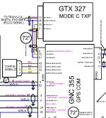
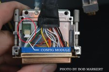
Problem 1. Mode C inoperative. There is valid ADHRS data with the G5 backup turned off, so the ADHRS unit is not the problem. Transponder Mode A seems to work. The transponder is wired to get altitude data on a dedicated serial line from the ADHRS. The transponder is not on the CANbus. ADS-B in shows relative altitudes, and those appear to be correct. I don’t know if any settings in the transponder were changed by Garmin. ATC did not comment on lack of Mode C during that short first flight in the pattern, but their radar is not necessarily all that good. Seems to me that there’s good data in the G3X Touch system, so the problem might be transponder bent pins, or something in the transponder got reset and they didn’t tell me, or wire damage, or…
Problem 2. ARINC channel 2 bug is still there. Fortunately, I have a listing of all the avionics settings. The only discrepancy I found was on the GTN650, ARINC 429 Out, the setting for ARINC 429 out 1 (yes, one) was set to Garmin 429. According to my notes, it used to be / should have been GAMA Format 1. It’s possible that this was a Garmin-recommended change that didn’t make it into my notes. Otherwise, all the ARINC 429 settings agree with my notes. And I’ve not yet steeled myself for battling the installation manual to double check the setting…
Problem 3 (solved). Somehow, the GTN Default Nav screen settings were completely changed. That was easy enough to fix, and I found that I could put a link to the VNAV page there as otherwise VNAV is a pain to drill down to in order to change. Only a slight hassle to find in the manual where to fix that, and with the VNAV link visible, this is an improvement.
So… no Mode C, no fly. And the rules for flying without ADS-B out are draconian, and it’s a pain to get a ferry permit to the radio shop.
ARINC bug? Apparently not serious, as, according to my notes, there’s no data sent on that channel, anyway. Curious, though…
Anybody got any ideas? Thanks in advance!
The chronology below is best as I remember, and I don’t want to cast aspersions on anybody as I don’t know exactly who did what when (some of this might have been me!), but here’s what I think was going on.
Everything was working fine before the fire, before the GTN and the transponder were sent to Garmin for soot removal after the fire.
On the first flight post-fire, the two G3X Touch screens had been swapped left and right by the maintenance shop. But that first flight was only two trips around the pattern, and swapping the screens back was an easy fix. There was also an error message, “Not receiving data on ARINC 429 channel 2.” I hoped that would go away with the screen swap.
Today’s flight was to a nearby airport to get gas, and to fly approaches to validate the avionics.
Problem 1. Mode C inoperative. There is valid ADHRS data with the G5 backup turned off, so the ADHRS unit is not the problem. Transponder Mode A seems to work. The transponder is wired to get altitude data on a dedicated serial line from the ADHRS. The transponder is not on the CANbus. ADS-B in shows relative altitudes, and those appear to be correct. I don’t know if any settings in the transponder were changed by Garmin. ATC did not comment on lack of Mode C during that short first flight in the pattern, but their radar is not necessarily all that good. Seems to me that there’s good data in the G3X Touch system, so the problem might be transponder bent pins, or something in the transponder got reset and they didn’t tell me, or wire damage, or…
Problem 2. ARINC channel 2 bug is still there. Fortunately, I have a listing of all the avionics settings. The only discrepancy I found was on the GTN650, ARINC 429 Out, the setting for ARINC 429 out 1 (yes, one) was set to Garmin 429. According to my notes, it used to be / should have been GAMA Format 1. It’s possible that this was a Garmin-recommended change that didn’t make it into my notes. Otherwise, all the ARINC 429 settings agree with my notes. And I’ve not yet steeled myself for battling the installation manual to double check the setting…
Problem 3 (solved). Somehow, the GTN Default Nav screen settings were completely changed. That was easy enough to fix, and I found that I could put a link to the VNAV page there as otherwise VNAV is a pain to drill down to in order to change. Only a slight hassle to find in the manual where to fix that, and with the VNAV link visible, this is an improvement.
So… no Mode C, no fly. And the rules for flying without ADS-B out are draconian, and it’s a pain to get a ferry permit to the radio shop.
ARINC bug? Apparently not serious, as, according to my notes, there’s no data sent on that channel, anyway. Curious, though…
Anybody got any ideas? Thanks in advance!
Last edited: