

I wasn't sure how to word the subject of this post, given the situation we're in today with the new Service Bulletin for rudder hinge bracket repair. But, I wanted to post this now, because I may be on to something that was missing in our RV-10 plans for many years now, and while doing the SB it would be the perfect time to remedy it. Hopefully someone from Vans will comment on this because it's got me scratching my head.
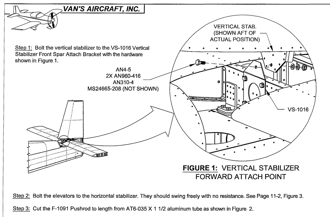
If you look at the RV-10 plans for Vertical Stabilizer attachment, you note that the forward end of the stabilizer mounts with a single bolt, secured with a castle nut and cotter pin. To me, this does imply the potential for rotational movement, and subsequent loosening of the nut. So that all makes sense.
Here is a clip from the plans: (Note that is is a Rev2, and I have no idea
which rev I used when building this back in 2005.
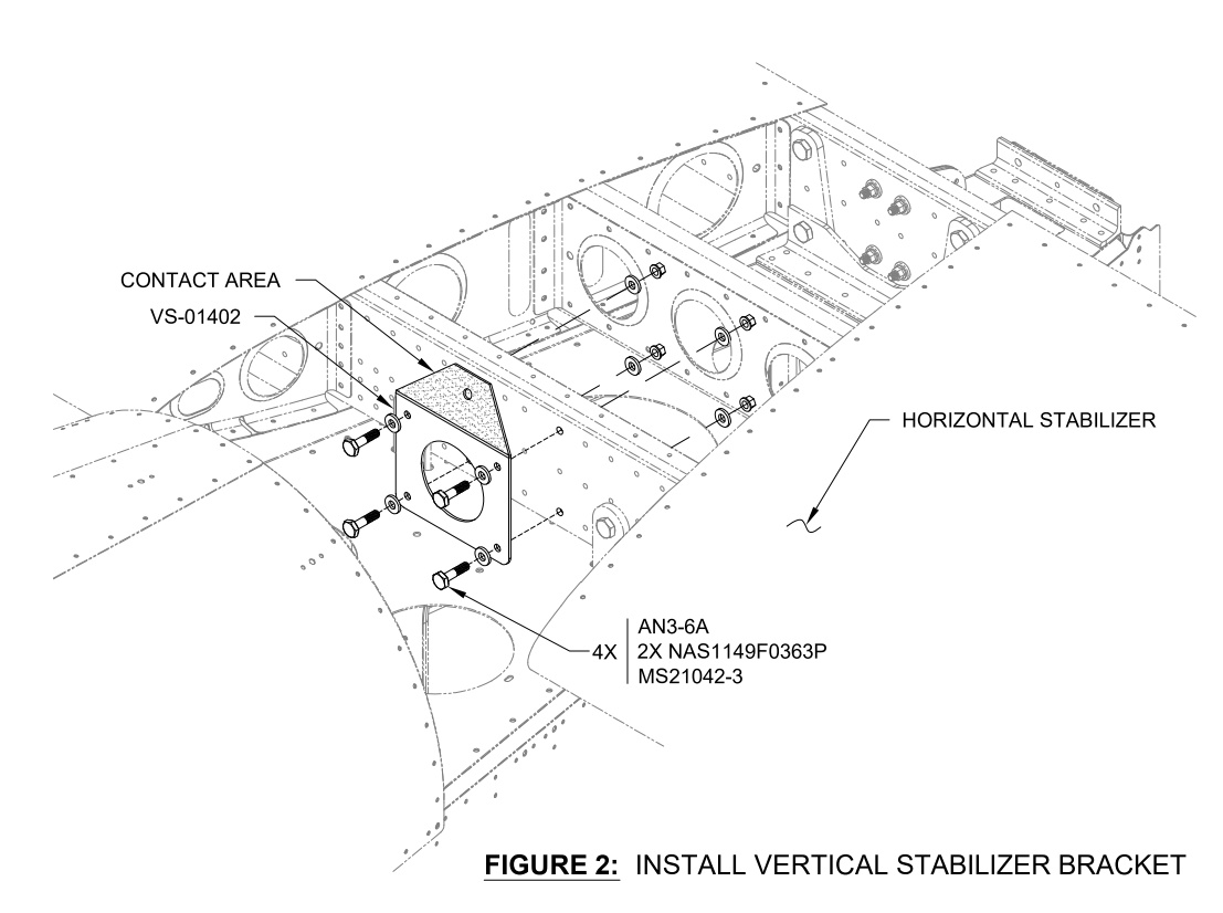
Now where it gets confusing is when you compare that to the basically identical situation of the RV-14.
Here is one pic from the same page in the RV-14 plans: (This page is a Rev 0 pic) Notice the "Contact Area" shown.
Now go on to page 11-8 on the RV-14 plans, which was Rev 2, and notice that it says to cover that contact area in anti-seize paste.
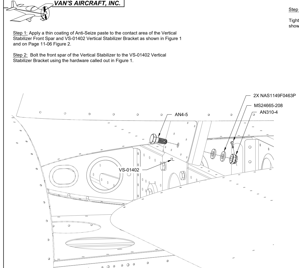
Ok, so maybe that movement is significant, and significant enough that you want to lubricate it? Or whatever they're protecting against with the anti-seize. What baffles me though, is why the RV-10 plans never mentioned this, but the RV-14 did, and, if the RV-14 plans are the correct thing to do, then why didn't the RV-10 plans ever receive this information...because I'm sure there are quite literally over a thousand RV-10's built that won't have any anti-seize on them.
As I said, this would be the perfect opportunity to rectify that, given that the new Service Bulletin requires removal of the vertical stabilizer. I would just like to hear if this is what we should all be doing, as part of that process.
Comments?
If you look at the RV-10 plans for Vertical Stabilizer attachment, you note that the forward end of the stabilizer mounts with a single bolt, secured with a castle nut and cotter pin. To me, this does imply the potential for rotational movement, and subsequent loosening of the nut. So that all makes sense.
Here is a clip from the plans: (Note that is is a Rev2, and I have no idea
which rev I used when building this back in 2005.
Now where it gets confusing is when you compare that to the basically identical situation of the RV-14.
Here is one pic from the same page in the RV-14 plans: (This page is a Rev 0 pic) Notice the "Contact Area" shown.
Now go on to page 11-8 on the RV-14 plans, which was Rev 2, and notice that it says to cover that contact area in anti-seize paste.
Ok, so maybe that movement is significant, and significant enough that you want to lubricate it? Or whatever they're protecting against with the anti-seize. What baffles me though, is why the RV-10 plans never mentioned this, but the RV-14 did, and, if the RV-14 plans are the correct thing to do, then why didn't the RV-10 plans ever receive this information...because I'm sure there are quite literally over a thousand RV-10's built that won't have any anti-seize on them.
As I said, this would be the perfect opportunity to rectify that, given that the new Service Bulletin requires removal of the vertical stabilizer. I would just like to hear if this is what we should all be doing, as part of that process.
Comments?
") Strange. Maybe someone can solve the mystery for us.
Strange. Maybe someone can solve the mystery for us.