My aft fuse is all match drilled and ready for disassembly, deburring, etc. Wondering about the rudder stops. I’m going to use the standard vans recommended stops. Just wondering if I should make them now and drill the tail, or is it best to wait until later in the build.

Van's Air Force
You are using an out of date browser. It may not display this or other websites correctly.
You should upgrade or use an alternative browser.
You should upgrade or use an alternative browser.
Rudder Stops- When to Drill
- Thread starter dwollen89
- Start date

Might want to Read this first.
Bottom line, the plans are wrong, the gap is the key thing to avoid rudder and elevator interference and damage.
Rudder stops and rudder deflection
I'm working on the rudder stops and start filing them to measurement. While doing so I stumbled upon these findings which are puzzling me. The manual says : " The proper 35 degree swing is attained when the clearance between the inboard trailing edge of the elevator skin and rudder skin is 1...
vansairforce.net
Bottom line, the plans are wrong, the gap is the key thing to avoid rudder and elevator interference and damage.
Been there, done that. 0 stars - Don’t recommend…
Get a cutting board and cut it to fit inside the bottom hinge bracket or buy the internal stop from Vince/Blake - Flyboys Accessories…

 flyboyaccessories.com
Get a cutting board and cut it to fit inside the bottom hinge bracket or buy the internal stop from Vince/Blake - Flyboys Accessories…
Internal Rudder Stop
Precision made internal rudder stop Features: Completely internal Easy bolt-on installation No protruding aluminum angle required on the fuselage sides Durable white HDPE construction won’t gall, rust, or wear Field tested and proven – hundreds sold and installed Although the photo shows the...
flyboyaccessories.com
I know a lot of folks feel that way, however I have the Van’s standard rudder stops on all three of our RV’s and never had a lick of problem. You do, of course, have to cut them to the right shape (which isn’t necessarily the shape on the plans).Been there, done that. 0 stars - Don’t recommend…
Get a cutting board and cut it to fit inside the bottom hinge bracket or buy the internal stop from Vince/Blake - Flyboys Accessories…
Internal Rudder Stop
Precision made internal rudder stop Features: Completely internal Easy bolt-on installation No protruding aluminum angle required on the fuselage sides Durable white HDPE construction won’t gall, rust, or wear Field tested and proven – hundreds sold and installed Although the photo shows the...
Fab them. Drill them. But don't rivet them. Put them away till final rigging.
I bought the Flyboy stop. I didn't realize how a tiny bit removed moves the stop position a lot. Needless to say, I had to buy my Sweetie a new cutting board. Her board gave it's life for a higher cause. I took three more before I got the stop perfect!
I bought the Flyboy stop. I didn't realize how a tiny bit removed moves the stop position a lot. Needless to say, I had to buy my Sweetie a new cutting board. Her board gave it's life for a higher cause. I took three more before I got the stop perfect!
I was originally thinking of doing that internal stop, but then I read somewhere that it was know to cause cracks. I can’t remember, but think it was Vans who said that. I made my stops per plans and riveted them on. Sounds like I may get to redo the shape of them once I put the rudder back on.
Somewhere between initial fitment and final installation I ended up with rudder stops that were slightly too short, allowing a bit too much rudder travel. I didn't want to go through the pain of drilling out and re-riveting new stops, so - with official blessing from Van's - I added "rudder stop extensions" just like the ones on the factory RV-9A (photo below). The screws are upside down to avoid interference with the rudder cables.
This works so well that I wish it was the default configuration: The tabs riveted to the fuselage ought to be one standard size, allowing you to much more easily fine-tune the geometry of the 1/8" thick extensions which perform the actual rudder-stopping. If I ever build another one of these machines I will probably just do this from the very start.

This works so well that I wish it was the default configuration: The tabs riveted to the fuselage ought to be one standard size, allowing you to much more easily fine-tune the geometry of the 1/8" thick extensions which perform the actual rudder-stopping. If I ever build another one of these machines I will probably just do this from the very start.
Wow, that’s good to know. Thanks for sharing. Judging from how much was added, the standard sized stop wouldn’t even be in the ballpark of what’s needed. Was that stop put in the callout location? It looks like there are rivets underneath it. The best I can tell, that’s not the case on mine.Somewhere between initial fitment and final installation I ended up with rudder stops that were slightly too short, allowing a bit too much rudder travel. I didn't want to go through the pain of drilling out and re-riveting new stops, so - with official blessing from Van's - I added "rudder stop extensions" just like the ones on the factory RV-9A (photo below). The screws are upside down to avoid interference with the rudder cables.
This works so well that I wish it was the default configuration: The tabs riveted to the fuselage ought to be one standard size, allowing you to much more easily fine-tune the geometry of the 1/8" thick extensions which perform the actual rudder-stopping. If I ever build another one of these machines I will probably just do this from the very start.
View attachment 74497
That I don't know, since this is from a photo sent to me by Van's tech support of one of their prototype airplanes.Judging from how much was added, the standard sized stop wouldn’t even be in the ballpark of what’s needed. Was that stop put in the callout location?
Before I was aware of this gotcha I cut my stops per plan, maybe even a 1/16th or so long. The plan was to clecoed them on and file them down to size when I rigged the rudder. Turns out they were waaaay too short and I had to remake them. If I had blindly just followed the dimensional callout it's 100% that the rudder would have hit the elevators.
I cut the replacements oversized, then filed them down a bit at a time until I got the correct travel.
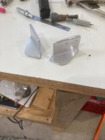
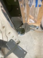
In the first picture the bogus one is on the left and the re-do is on the right. In the second picture the re-do one is being trial fit. I can't remember if it's final size in that picture, but it's close. It's in the called out location.
I cut the replacements oversized, then filed them down a bit at a time until I got the correct travel.
In the first picture the bogus one is on the left and the re-do is on the right. In the second picture the re-do one is being trial fit. I can't remember if it's final size in that picture, but it's close. It's in the called out location.
Attachments
Thanks for the info. I made my stops per the instructions already. I’m guessing they won’t be usable once I need them but I’ll use them for a template to drill the holes now. Did you use four An470AD4 rivets to attach them? I’m wondering how a 1/8 hole wont violate the edge distances on the bulkhead flanges.Before I was aware of this gotcha I cut my stops per plan, maybe even a 1/16th or so long. The plan was to clecoed them on and file them down to size when I rigged the rudder. Turns out they were waaaay too short and I had to remake them. If I had blindly just followed the dimensional callout it's 100% that the rudder would have hit the elevators.
I cut the replacements oversized, then filed them down a bit at a time until I got the correct travel.
In the first picture the bogus one is on the left and the re-do is on the right. In the second picture the re-do one is being trial fit. I can't remember if it's final size in that picture, but it's close. It's in the called out location.
I just went with the fastener callout per print 27A. The aft two holes are AN426AD4's and the fwd two are CS4-4."...Did you use four An470AD4 rivets to attach them? I’m wondering how a 1/8 hole wont violate the edge distances on the bulkhead flanges..."
In this case it doesn't matter if it violates the generic 2d edge distance practice or not. When it exists, manufacturers engineering supersedes generic guidance like that.
I went back and looked at my build entry to see approximately how much bigger I ended up making these and in my case the aft tabs needed to be about 3/8 longer than the print callout. Here's a link to that entry in my build manual.
EAABuildersLog.org - Free aircraft builders log website.
EAABuildersLog.org is a airplane builders log website to store your projects on the web for free. The EAA (Experimental Aircraft Association, Inc.) provides this website for it's members for free..
 eaabuilderslog.org
Last edited:
