So, I know that many opt to remove the jettison handle for several reasons, but I am not getting any younger, and down the road, if I wanted to remove the canopy without becoming a contortionist, I opted to "relocate" the handle vs removing it. I also wanted the free up the real estate in the center panel for a more traditional "center stack" as well as provide the means to open up the subpanel behind the stack. I did so using the RV-14 kit parts (not the full kit) to save on not having extra stuff I'd never use.
Reference OP-63 at Vansaircraft.com
Materials list:

Next was the trimming of the F-697 Channel to remove interference with the future hole in the F-768 Subpanel for a center stack, as well as the direction reverse of the WD-619. I also removed a bit more material on the C-620 Bearing Block to clear the pivoting hardware and Release Links (the listed dimensions didn't seem to clear even the stock setup). I also located and cutout the clearance reliefs in the F-697 and F-643-1 for the bolt and right-hand Release Link.

Next, the critical dimension to find/set is the placement of the F-14193 and where it goes on the F-643-1 FWD Fuselage Channel. I determined mine to be 5 1/16" aft of the firewall to the forward edge of the F-14193, centered on the web (or so) from top to bottom. This then created the 4 1/2" gap needed from the mounting hole for the cable/clamp to the rear position stop location of the WD-618-1, allowing for the cable sleeve length called for in the OP-63 plans.

Because of the direction of the assembly pivot "reversing", the lengths of the C-621 and the C-622s "may" work, but since I was starting fresh, I measured and verified and determined that they needed to be longer.

The above was a snip from DWG 47, MODIFIED with my measured lengths (YMMV). I then tossed this and the material off to a machinist friend of mine who was dead nuts on accurate.

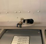
With the WD-618-1-PC full AFT and just flush with the F-768 Subpanel hole for the original handle hardware, my AN43B-16 Release Pins are FULLY seated. Full FOWARD (the pulled cable position) the pins retract and clear the slot perfectly.
See the smooth action below:
Hopefully, if others desire to do the same, the above will help save you time and give you some ideas. Enjoy!
Reference OP-63 at Vansaircraft.com
Materials list:
- WD-618-1-PC - Canopy Release Assembly, Powder Coated (if undrilled, you can use the WD-618-PC that came in your finish kit). They are effectively the same, save 2 bends that the 14 has in its WD.
- F-14193 - Canopy Release Handle Mount
- TOOL-00092 - Drill Template, Canopy Release
- F-01452D - Anchor, Security Wire
- AN320-3 - AN320-3 Nut, Castle, Shear
- AN931-4-12 - AN931-4-12 Grommet
- CT A-740 CABLE CLAMP - Bowden A-740 Cable Clamp
- NAS1149F0332P (5) - Flat Washer, Thin, 3/16" ID (#10 Screw) - You only need 3
- VA-181-1 - Wire Nut - you will need to source a Stainless 10-32 x 3/8" or 1/4" setscrew from the HD/Lowes aircraft hardware store
- CT A-1770 - T-Handle Cable, 72"
Next was the trimming of the F-697 Channel to remove interference with the future hole in the F-768 Subpanel for a center stack, as well as the direction reverse of the WD-619. I also removed a bit more material on the C-620 Bearing Block to clear the pivoting hardware and Release Links (the listed dimensions didn't seem to clear even the stock setup). I also located and cutout the clearance reliefs in the F-697 and F-643-1 for the bolt and right-hand Release Link.
Next, the critical dimension to find/set is the placement of the F-14193 and where it goes on the F-643-1 FWD Fuselage Channel. I determined mine to be 5 1/16" aft of the firewall to the forward edge of the F-14193, centered on the web (or so) from top to bottom. This then created the 4 1/2" gap needed from the mounting hole for the cable/clamp to the rear position stop location of the WD-618-1, allowing for the cable sleeve length called for in the OP-63 plans.
Because of the direction of the assembly pivot "reversing", the lengths of the C-621 and the C-622s "may" work, but since I was starting fresh, I measured and verified and determined that they needed to be longer.
The above was a snip from DWG 47, MODIFIED with my measured lengths (YMMV). I then tossed this and the material off to a machinist friend of mine who was dead nuts on accurate.
With the WD-618-1-PC full AFT and just flush with the F-768 Subpanel hole for the original handle hardware, my AN43B-16 Release Pins are FULLY seated. Full FOWARD (the pulled cable position) the pins retract and clear the slot perfectly.
See the smooth action below:
Hopefully, if others desire to do the same, the above will help save you time and give you some ideas. Enjoy!