A few suggestions
I had the earlier non-prepunched baffle kit and made a lot of changes at the oil cooler connection due to the fact that I have spent so much time repairing baffles on certificated aircraft. The standard Vans design is virtually guaranteed to fail in that area. This is what I did.
1. I threw out the standard Vans oil cooler "flange" and fabricated a new beefier one from 0.032 sheet. See pix 1.
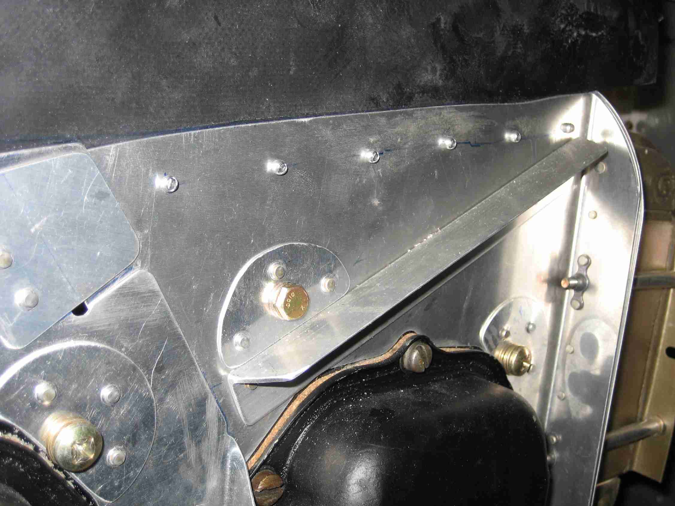
2. I fabricated an outboard corner reinforcement angle from 0.064 sheet. See pix 2.
3. I fabricated an infill section above the oil cooler to stiffen up the area and allow the rubber to run in a straight line in that area (this infill was ultimately provided with the newer prepunched kit). See pix 4.
4. I used 3 bolts on the outboard side and 2 bolts on the inboard side of the oil cooler. See pix 3.
5. I fabricated special "washers" to distribute the bolt/tube loads at the oil cooler flanges. See pix 3.
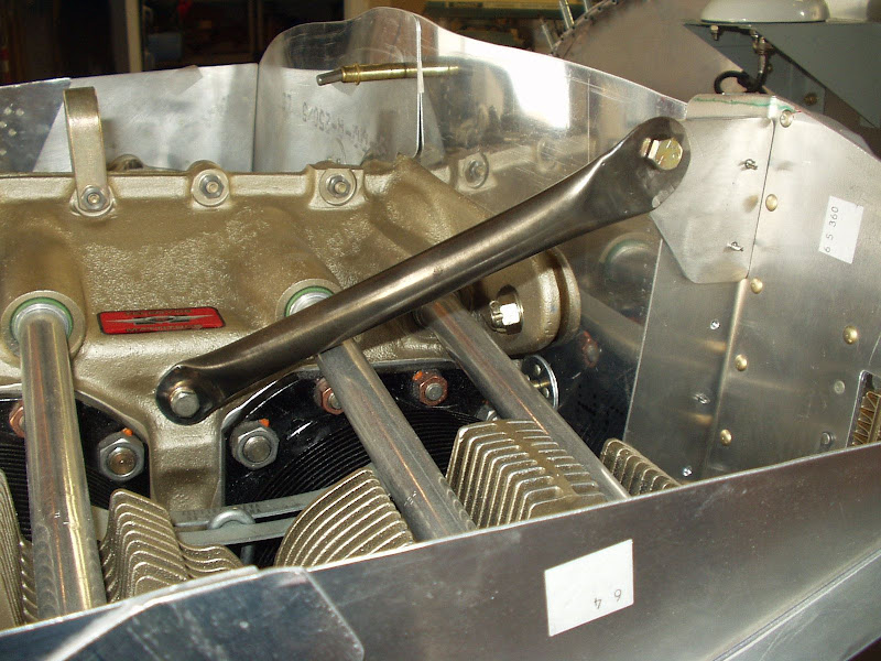
6. I fabricated a brace to triangulate the oil cooler back to the #4 cylinder head.
I have a few additional comments on this last detail. .
a) I wouldn't run this brace to the #2 cylinder as some have done due to the thermal expansion of the engine (as others on this thread have rightly pointed out).
b) The optimum place to connect the brace at the oil cooler end is
onto the oil cooler bolts themselves. This ensures that no oil cooler loads are transmitted through the baffle sheeting at all.
c) It is ideal to pick up 2 bolts at the oil cooler and fabricate the attachment bracket such that the brace strut is coincident with the centre-line of the oil cooler bolts. This will eliminate any eccentric forces that might tend to produce cracking over time.
I've attached a few pix to show these details.
Pix 1. New oil cooler flange.
 Pix 2.
 0.064 corner angle.
 Pix 3.
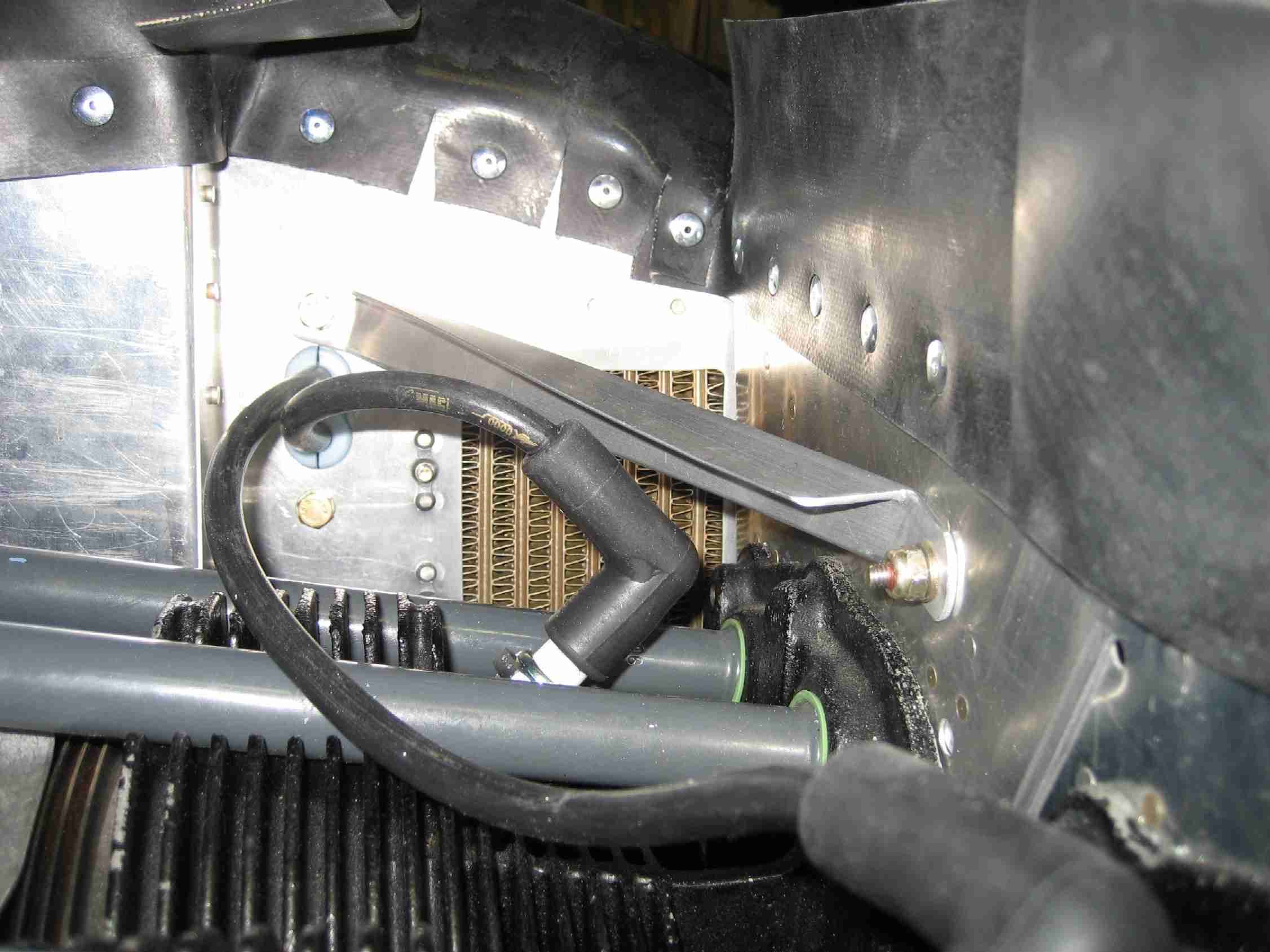
 Five bolts used on cooler (note load distribution "washers".
 Pix 4.
 Cooler brace to #4 cylinder (note also infill above cooler for extra stiffness). Note that temporary nylock nuts will be replaced with metal locknuts.


 That's 1/8" thick angle!