



Hello all-
I’m getting close (6 weeks out) from the planned panel / electrical system upgrade in my F1 Rocket.
I’ll be installing a (mostly) Dynon IFR panel in my F1 Rocket. It will include Dynon’s Advanced Control Module as a power distribution source for most components. I already have (newly-installed and functioning) 60A B&C alternator and a 30A Monkworkz backup generator (comes online when battery voltage drops below a preset level).
I read Knuckolls’ book a while back, but didn’t really see a recommended system for a backup power source with automatic load-shedding.
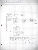
My idea is to have the alternator power a “Non-Essential bus” with current then passed through a diode to the “Main Bus.” The backup generator would only power the “Main Bus” when it operated.
(See attached sketch in PDF and photo formats)
The Main Bus would provide power to the ACM (all avionics & lights) and a 12V outlet in the cockpit that will run an oxygen generator.
The Non-Essential bus would power all other “high draw” items like seat heaters and USB chargers - things that would exceed the capacity of the 30A backup generator.
I haven’t seen a diagram for a power distribution system like this, and want to make sure that there isn’t a good reason that it hasn’t been done before.
(Or maybe I just haven’t been looking in the right places).
The only flaw that I can think of is that it’s dependent on the diode functioning to pass power from the Non-Essential bus to the Main bus. If that diode were to fail and not conduct electricity, I’d be down to my backup generator to power the Main bus. If the diode were to fail to prevent flow from the Main bus to the Non-Essential bus, I’d have to load-shed manually by pulling circuit breakers for all the high-load accessories when operating on the backup generator alone.
What other flaws am I missing?
Edited to add:
I see that I’m not far off of Knuckolls’ Z-12 design. Except that my design has the backup generator powering the “Main bus” (kind of like Knuckolls’ “E-bus”) directly. AND - my Main bus will draw more amps (up to 30) than Knuckolls’ recommended E-bus draw of 3-4 A.
So- maybe the challenge is finding a diode that will support a continuous current of 30A without overheating.
Ideas anyone?
I’m getting close (6 weeks out) from the planned panel / electrical system upgrade in my F1 Rocket.
I’ll be installing a (mostly) Dynon IFR panel in my F1 Rocket. It will include Dynon’s Advanced Control Module as a power distribution source for most components. I already have (newly-installed and functioning) 60A B&C alternator and a 30A Monkworkz backup generator (comes online when battery voltage drops below a preset level).
I read Knuckolls’ book a while back, but didn’t really see a recommended system for a backup power source with automatic load-shedding.
My idea is to have the alternator power a “Non-Essential bus” with current then passed through a diode to the “Main Bus.” The backup generator would only power the “Main Bus” when it operated.
(See attached sketch in PDF and photo formats)
The Main Bus would provide power to the ACM (all avionics & lights) and a 12V outlet in the cockpit that will run an oxygen generator.
The Non-Essential bus would power all other “high draw” items like seat heaters and USB chargers - things that would exceed the capacity of the 30A backup generator.
I haven’t seen a diagram for a power distribution system like this, and want to make sure that there isn’t a good reason that it hasn’t been done before.
(Or maybe I just haven’t been looking in the right places).
The only flaw that I can think of is that it’s dependent on the diode functioning to pass power from the Non-Essential bus to the Main bus. If that diode were to fail and not conduct electricity, I’d be down to my backup generator to power the Main bus. If the diode were to fail to prevent flow from the Main bus to the Non-Essential bus, I’d have to load-shed manually by pulling circuit breakers for all the high-load accessories when operating on the backup generator alone.
What other flaws am I missing?
Edited to add:
I see that I’m not far off of Knuckolls’ Z-12 design. Except that my design has the backup generator powering the “Main bus” (kind of like Knuckolls’ “E-bus”) directly. AND - my Main bus will draw more amps (up to 30) than Knuckolls’ recommended E-bus draw of 3-4 A.
So- maybe the challenge is finding a diode that will support a continuous current of 30A without overheating.
Ideas anyone?
Attachments
Last edited:
