What's new
Van's Air Force

Don't miss anything! Register now for full access to the definitive RV support community.

Pictures of RV-9A or RV-7A manifold pressure/oil pressure/ fuel pressure hoses

terrye

Well Known Member
I've studied Vans OP-28 Carbureted Fuel System, OP-32 IO-360 Fuel System, and OP-27 Oil System drawings but these do not include the routing or any other information for the manifold pressure line. I also have Vans IE VMP Install Kit, however this is mainly for use with Vans analog manifold pressure gauge.

I will be plumbing the Oil System per Vans OP-27 drawing.
I'm looking for pictures of the manifold pressure hose and routing from the engine to the VA-168 Transducer Manifold. Does the hose route along the same path as the Vans VA-132 Oil Pressure Hose?

Also looking for pictures of the fuel pressure hose, but on my airplane there is a twist. I'm using a dual battery setup and so I have a PC-680 on each side of the firewall recess (mirror image of DWG 31A ES PC-680 Install Kit). So the routing of the fuel pressure hose is compromised by the location of the second battery.

Thanks for your help
 
Last edited:
Get your popcorn handy;

Why not just use one battery and have a standby alternator/generator? simpler, lighter, more reliable, etc.?

Ok, on to the routing --

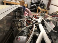
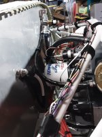
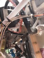
Oil Pressure and MAP lines run parallel to each other, secured to the top of the firewall recess with cushion clamps (adel clamps) at two places. Fuel pressure is a straight shot up from the restrictor 45 on the fuel pump. All hoses are custom lengths, thanks to PHT out of Tulsa OK.

IMG_1785.jpegIMG_1325.jpeg
 
Why not just use one battery and have a standby alternator/generator? simpler, lighter, more reliable, etc.?
After reading Bob Nuckolls' Aeroelectric Connection I seduced myself into "needing" the Z-14 electrical system. So yes, I have a 60A main alternator, a 30A standby alternator (driven off the vacuum pump pad), dual batteries and split bus. Also seduced myself into "needing" an IFR instrument panel (dual nav sources, dual nav radios in Canada). Decisions made a long time ago. But as everyone who has gone "off plans" knows, this adds exponentially to the time (and money).

Thanks for the pictures, most appreciated. Keep them coming.
Terry, take note that other builders may not share the same accessory locations as you , like Brians pic. He has a firewall mounted remote cooler. Others also may have a remote cooler, but in a different place, and use different hose lengths and routings. Give us some more information on yours and Im sure we have pics to help.
Tom
 
Thanks Tom. My oil cooler will be per Vans OP-27, left rear baffle mount, so standard length oil cooler hoses on my IO-320. Not concerned with those at the moment as my engine is not mounted yet. I wanted clarification on the manifold pressure sensor line as this is not addressed by Vans and Brian's pictures are quite helpful. Additional pictures would be nice. With my dual battery setup, it's not clear what the best routing is for the fuel pressure sensor line from the mechanical fuel pump to the VA-168 sensor manifold. This may have to wait until the engine is mounted but of course the access is more limited then.
 
Thanks Tom. My oil cooler will be per Vans OP-27, left rear baffle mount, so standard length oil cooler hoses on my IO-320. Not concerned with those at the moment as my engine is not mounted yet. I wanted clarification on the manifold pressure sensor line as this is not addressed by Vans and Brian's pictures are quite helpful. Additional pictures would be nice. With my dual battery setup, it's not clear what the best routing is for the fuel pressure sensor line from the mechanical fuel pump to the VA-168 sensor manifold. This may have to wait until the engine is mounted but of course the access is more limited then.
well if the second battery is under the sendor manifold, maybe but I doubt it. There is enough lenght in the stock hose to change the routing. I tell builders to install the accessories as the need---then figure out the plumbing. MUCH easier than moving a battery or cooler, or whatever else. AND you can always use a custom hose.
 
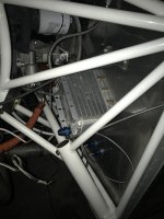
Here are some pics. The manifold pressure line runs from the primer port on #3 cylinder to the Dynon transducer that is on the right hand side of the firewall.

20240717_085057.jpg20240717_085106.jpg

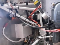
The oil pressure line is per Van's drawing and runs from the engine to an Adel clamp on the firewall and then to the transducer manifold.

20240717_085144.jpg

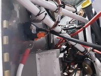
The fuel pressure line runs from the 45 degree restrictor fitting on the fuel pump outlet tee fitting up to the transducer manifold. If there was another battery box then there would be interference, if it was in the same relative position as the standard tailwheel battery box. But if the second battery box was located further outboard and lower down then I think the hose should clear the battery. The first battery cannot go lower down because the solenoids are in the way and it needs to be inboard enough to fit the battery past the engine mount tubes.
20240717_085207.jpg
 
Back
Top