
Van's Air Force
You are using an out of date browser. It may not display this or other websites correctly.
You should upgrade or use an alternative browser.
You should upgrade or use an alternative browser.
P Mag Test Switch
- Thread starter rockitdoc
- Start date

Mark33
Well Known Member
Honeywell TL double pole, three position.
I used two Honeywell TL switches. They were double pole, three position switches...(off/on/momentary off). They also had a lockout between on and off. The lockout required the lever(s) to be pulled out to put the switch in the full off position. With the switches configured this way, it allowed me to do all of the preflight mag checks but made it impossible to inadvertently turn either switch off during flight.
I used two Honeywell TL switches. They were double pole, three position switches...(off/on/momentary off). They also had a lockout between on and off. The lockout required the lever(s) to be pulled out to put the switch in the full off position. With the switches configured this way, it allowed me to do all of the preflight mag checks but made it impossible to inadvertently turn either switch off during flight.
Last edited:
Carl Froehlich
Well Known Member
Toggle for P-lead, breaker above it for power.
+1
Simple solution for a simple issue.
Carl
JeremyL
Well Known Member
http://https://www.steinair.com/product/locking-toggle-switch-p-mag-test-on-on-mom/
What switch/buttons did you use?
vlittle
Well Known Member
I used a three position toggle switch. Down mag cold - is p-lead open (off), power off. Up is mag hot- p-lead grounded, power on, center is test- p-lead grounded, power off.
Works for me.
Are you sure? Looks like you have the p-lead logic reversed.
YellerDaisy
Well Known Member
Toggle for P-lead, breaker above it for power.
Ditto for me. Simple.

Walt
Well Known Member
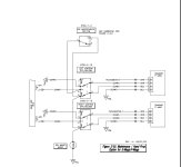
Using the Stein Switch
MOM Test (Up): E-Mag Power interrupted. Ignition On (P-Lead Open)
Center: E-Mag Power On, Ignition On (P-Lead Open)
Down: Power On, Ignition Off (P-Lead) Grounded)
View attachment 44544
Don’t forget to turn off the ‘other mag’ when doing this test.
Hard to understand how the above makes sense or makes things simpler, you still need breakers for power.

Iluke
Well Known Member
Are you sure? Looks like you have the p-lead logic reversed.
Yes, you are right of course. P-lead is grounded in the down—off position, open in the up and middle positions
Thanks for the catch
finack
Member
I was wondering this too Walt. I guess it comes down to when do you want to have the mains on and not have power to the pmags? Or to say it a different way when do you want the power off & p-lead grounded?
Don’t forget to turn off the ‘other mag’ when doing this test.
Hard to understand how the above makes sense or makes things simpler, you still need breakers for power.
David Paule
Well Known Member
Scott, email sent.
Dave
Dave
Two toggles, L and R P-leads, two normally closed push button switches for L and R P-mag power.
Mixture full rich, run up the the engine 1800 rpm.
Flip off R P-lead, push L button to remove ship’s power from L P-mag, release button, Flip on R P-lead.
Flip off L P-lead, push R button to remove ship’s power from R P-mag, release button, flip on L P-lead.
Throttle to idle, mixture lean.
Mixture full rich, run up the the engine 1800 rpm.
Flip off R P-lead, push L button to remove ship’s power from L P-mag, release button, Flip on R P-lead.
Flip off L P-lead, push R button to remove ship’s power from R P-mag, release button, flip on L P-lead.
Throttle to idle, mixture lean.

BOHICA
Well Known Member
Don’t forget to turn off the ‘other mag’ when doing this test.
Hard to understand how the above makes sense or makes things simpler, you still need breakers for power.
Actually don't turn off the other Emag when doing this test. If the other mag is off and this test fails your engine stops. When running this test if it fails if you see an RPM drop this would due to the loss of the internal E-Mag power source which you are verifying when you go to the MOM up position. See the internal power transition of E-Mags https://emagair.com/114-series/.
Test procedure.
Engine running
Right Mag Switch down observe RPM drop
Return Right Switch to center RPM should return to normal.
Right Switch Up (MOM) observe no RPM drop (tests E-Mag internal Power source is working).
Release switch which will automatically return to center position.
Repeat for Left Mag.
Switches are not for power protection. Switches are for Power control. There are fuses in the system just not shown in the schematic provided.
The simplicity is that you have one switch per mag to test each mag with.
The system I have uses a push button to start engine (Midwest Intellikey system) the switches are need to test E-Mags. https://www.youtube.com/watch?time_continue=121&v=mi-mbDHIwgc&embeds_referring_euri=https%3A%2F%2Fwww.bing.com%2F&embeds_referring_origin=https%3A%2F%2Fwww.bing.com&source_ve_path=Mjg2NjY&feature=emb_logo. If you look carefully in the video you actuall see the two test switches above the start button.
If you are using a key (Cessena'ish) with off-Left-Right-Run-Start then you need a different switch for E-Mag Power On-and Off which is what you are thinking it sounds like.
BOHICA
Well Known Member
I used the Aeroelectric 3-position switch design (OFF/ON/BAT) with a single switch to place both Pmags in setup mode for timing.
No issues 11+ years.
I can do basically the same thing using my VPX that supplies power to the EMAGS.
What switch/buttons did you use?
Just adding don't over engineer this, all you're trying to do is interrupt ships (battery) power to make sure the PMAG generators are working.
So whatever switch you use it should go between each PMAG breaker its P lead.
When you test, nothing should change. If you get an RPM change, you have a potential PMAG generator problem.
You can just pull the PMAG breakers but it's cumbersome and they aren't really designed for constant usage.
I can do basically the same thing using my VPX that supplies power to the EMAGS.
This is what I use. On the VP-X menu from the Skyview I can toggle on/off the L and R P-Mag circuits from the EFIS. No need for extra toggle switches on the panel.
Dad's RV-10
Well Known Member
Actually don't turn off the other Emag when doing this test. If the other mag is off and this test fails your engine stops. When running this test if it fails if you see an RPM drop this would due to the loss of the internal E-Mag power source which you are verifying when you go to the MOM up position. See the internal power transition of E-Mags https://emagair.com/114-series/...
This is straight from the manual:
1) Ramp Checks (roughly 1700 RPM).
a) Internal Alternator - E-MAG internal alternator operates in parallel with power supplied by the aircraft bus. The ignition automatically transitions between aircraft power and internal alternator power as needed. Aircraft power is required for starting and low idle speeds.
i) Running on one ignition only, turn ignition power test switch OFF for 2-3 seconds and back ON. The engine should run smooth during the momentary bus power outage, verifying the internal alternator is working.
ii) Repeat with the other ignition.
iii) The left/right Ramp Check rpm drops may be quite a bit different with E-MAGs than magnetos. We don’t apply the same rules to gauge ignition health. Any rough or degraded behavior (before, during, or after each side’s Ramp Check) indicates a problem - not suitable for flight.
Last edited:
BOHICA
Well Known Member
This is straight for the manual:
1) Ramp Checks (roughly 1700 RPM).
a) Internal Alternator - E-MAG internal alternator operates in parallel with power supplied by the aircraft bus. The ignition automatically transitions between aircraft power and internal alternator power as needed. Aircraft power is required for starting and low idle speeds.
i) Running on one ignition only, turn ignition power test switch OFF for 2-3 seconds and back ON. The engine should run smooth during the momentary bus power outage, verifying the internal alternator is working.
ii) Repeat with the other ignition.
iii) The left/right Ramp Check rpm drops may be quite a bit different with E-MAGs than magnetos. We don’t apply the same rules to gauge ignition health. Any rough or degraded behavior (before, during, or after each side’s Ramp Check) indicates a problem - not suitable for flight.
And if the internal alternator is not working with the other ignition is off your motor stops running. Does that make sense as a logical thing you want to do ? Nope Already pinging them about this and I have talked to a couple of other places doing installs and the method I explain is what they say. Manuals do get things wrong from time to time.
Not addressing your question, but here's how I did my PMAG wiring.
http://www.rv8.ch/dual-pmag-wiring/
http://www.rv8.ch/dual-pmag-wiring/
Bill posted an excellent diagram here:
https://vansairforce.net/community/showpost.php?p=1365992&postcount=7
https://vansairforce.net/community/showpost.php?p=1365992&postcount=7
dmattmul
Well Known Member
Or an EFI system (EFII or SDS)
And if the internal alternator is not working with the other ignition is off your motor stops running. Does that make sense as a logical thing you want to do ? Nope
I think I'd rather have my "motor stops running" on the ground than in the air, Yep?
This thread makes me glad I have mags
And if the internal alternator is not working with the other ignition is off your motor stops running. Does that make sense as a logical thing you want to do ? Nope
I think I'd rather have my "motor stops running" on the ground than in the air, Yep?
If you use buttons to test your P Mags, what hardware did you select? I was going to use an Otto P3 for mine, but the contacts are so small, they did not seem robust enough.
Compare to a Honeywell TL:
View attachment 44572
Did anyone actually answer rocketdoc's question? (didnt see it)
Im interested in the answer.
wirejock
Well Known Member
Switches
I don't think so.
I used two Honeywell TL
https://www.steinair.com/product/locking-toggle-switch-p-mag-test-on-on-mom/
Not sure if they will work with Scott's set up
Mine are wired from the Master through two breakers.
Did anyone actually answer rocketdoc's question? (didnt see it)
Im interested in the answer.
I don't think so.
I used two Honeywell TL
https://www.steinair.com/product/locking-toggle-switch-p-mag-test-on-on-mom/
Not sure if they will work with Scott's set up
Mine are wired from the Master through two breakers.
rapid_ascent
Well Known Member
I used an Otto switch for my TO/GA switch. It is a P1 type, but I believe it has the same small terminals. I did order some PIDG crimp ring terminals for these contacts. My personal opinion is I wouldn't consider the size of the terminals to be the determining factor of the switch's robustness. Otto switches are high quality switches, but I think it is up to each of us to make our own decisions on these things. Everyone has different comfort levels.
This question . . .
If you use buttons to test your P Mags, what hardware did you select?
Just replied to a PM from the OP. It’s a switch from DigiKey, but the exact part is in my big book of receipts in the hangar. This may be the part, or a close equivalent: https://www.digikey.com/en/products/detail/electroswitch/7084C/2679594
FWIW, was able to check: that is the push button switch I used.
Last edited:
I assume Scott is looking for a push button, SPST, momentary, normally closed switch. My concern is how does a switch like that fail. Open or closed? Hopefully closed.
If the bus power to the pmag was never supplied, what happens? Is one working mag enough to start the engine and internally power the disconnected pmag, and you'd never know without seeing the LEDs?
I suppose you could do a second ground check, with bus power ON, running below the RPM required for internal power...

