What's new
Van's Air Force

Don't miss anything! Register now for full access to the definitive RV support community.

Over voltage question

KiloWhiskey1

Well Known Member
I just swapped out a slick mag and lightspeed ignition for two Surefly SIMs. I test flew the plane last week and then flew a 20 minute flight to the North Georgia mountains for a weekend camping trip. I had no issues on those two flights but on the flight home I had ongoing over voltage warnings. The voltage moved between 14v and 15.5v. The mountain mornings began with significant fall dew which I thought may have contributed to the issue, however I let the plane sit for three days and had the same issue today. I’m using a plane power internally regulated 60 amp alternator with an Odyssey PC925 primary batt and 4 6v 12Ah werker batteries in series/parallel for backup power. This setup worked flawlessly for the past 150 hours.

I know it could be the internal voltage regulator. What else comes to mind in situations like this?
 
I assume batteries are not connected to eachother with BAT-switch in the OFF possition and SIMs connected directly to each battery.
With the ignition switch in the OFF position, the current draw of the SIMs is micro-amps. However if you accidently leave the ignition switch in L or R or
Both possition, the current draw icreases to about 0,6 A for each SIM.
If one of the SIMs drained the non starting battery compleatly, this may be the
the problem you see. I would check battery voltage.

Good luck
 
See post #2. With the plane power alternator, the wire (and usually switch/Circuit breaker) that supplies the field current is also used as the buss voltage sense wire. Take a voltmeter and look for any voltage drop from buss to alternator. (Bad connection, failing switch or CB, etc). Sometimes just removing a connection and re-installing will magically fix the problem (it was slightly loose, or you scrape off a tiny bit of corrosion, etc)
 
too much resistance on the sense wire for the VR


The "sense" wire is a loop of wire between two pins (Field and Sense) on the Alternator.

I'd be looking at a failed/failing Alt-Field switch. Same issue -- resistance is increasing resulting in a lower than expected voltage on the Sense/Field input.
 
The "sense" wire is a loop of wire between two pins (Field and Sense) on the Alternator.

I'd be looking at a failed/failing Alt-Field switch. Same issue -- resistance is increasing resulting in a lower than expected voltage on the Sense/Field input.

Should have been more clear. THe alt needs to read the bus voltage so it can regulate. Some how this voltage needs to get from the bus to the alternator. Don't know PP, but assume it comes from the fld wire, which is just called a field wire but more likely a regulator power source as the field is fed and controlled by the internal regulator. Therefore need to follow that wire from the PP ALL THE WAY back to the bus. For me, it was a loose screw on the Fld CB. Resitance anywhere in this path will trick the alternator into thinking the voltage is lower than it really is and up it's output on the B lead, leading to the OV condition.

The PP has a few VERY common failure points, so do your research and be sure it is not one of those causing this issue.
 
Last edited:
Update:

After reading all the replies I tried a few things that were suggested or hinted at.

I started by testing voltage and resistance. With the engine off the battery tested 12.65v, the split master and field wire tested 12.35v at the panel, and the B lead and field wire both showed 12.35v at the alternator. The field wire had virtually no resistance (0.3 ohms).

I charged both batteries overnight with an oddysey 20amp conditioning charger. I thought this would minimize the chance that one battery was confusing the voltage regulator. I ran it with main battery only and then with the backup batt and main. In both configurations I’m still getting 15.3v while above 1500rpm and 14.9v at idle.

I did the best I could to check for loose connections on all switches and breakers and confirmed all the field, master, and alternator connections were solid.

Any other suggestions before concluding the alternator’s internal regulator is to blame?
 
Last edited:
Update:

. The field wire had virtually no resistance (0.3 ohms).

Carefull....the field circuit may draw something like 4 amps if the alternator is trying hard to charge. 4(amps) times 0.3(ohms) = 1.2 volts, almost exactly the size of your problem.
 
Plane Power 99-1012 12v/60a troubleshooting

After exhausting the troubleshooting steps that have been discussed below, I called Plane Power to get their opinion. Below are the steps that they recommend to troubleshoot their internally regulated alternators. Maybe this will help someone else with alternator issues.

Unplug field wire connector from alternator (this changed my previous readings)
Check voltage at these spots with master and alternator switches on:
Check buss voltage going in to field circuit breaker (mine was 12.42v)
Check voltage at circuit breaker from out post (mine was 12.42v)
Check voltage on both sides of master (12v in and field wire out) - (mine was 12.39v in 12.39v out)
Check voltage at alternator field wire (mine was 12.39v)
Check voltage at B+ wire on alternator (mine was 12.39v)

If there are significant voltage losses between any of these points then check connections and consider replacing the components that are causing the voltage drop (ie wire, connectors, circuit breaker, or master switch). If there are minimal voltage drops between the above points then:

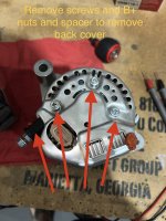
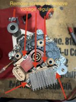
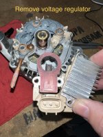
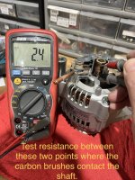
Remove alternator, then remove B+ nuts and black spacer and three screws in order to remove back cover, then remove 5 screws to remove voltage regulator assembly. Copper around shaft is slip ring on center shaft and needs to be tested for resistance. Two dark wear lines on it are where the carbon brushes from the voltage regulator assembly contact the spinning shaft. Test the two dark carbon lines for resistance. 3-8ohms resistance would tell you that the alternator is okay but regulator is bad. zero or over 100 ohms means alternator is bad.

Resistance on my slip ring was 2.3 - 2.6 ohms. While slightly out of the 3-8 ohm range, the tech thought the reading meant the alternator was okay and the problem was most likely the voltage regulator. They are sending me a new voltage regulator to see if that resolves the issue.

IMG_5967.jpg
IMG_5968.jpg
IMG_5969.jpg
IMG_5965.jpg
 
Last edited:
Carefull....the field circuit may draw something like 4 amps if the alternator is trying hard to charge. 4(amps) times 0.3(ohms) = 1.2 volts, almost exactly the size of your problem.

THIS ^

.3 is too much. Seems insignificant to the novice, but Bob nailed it here. Some meters are a bit imprecise, so we accept .1 as 0, but there is a meaningful difference between 0 and .3 that matches your problem.

VR's almost never fail in a way that matches your symptoms.
 
Last edited:
Voltage measurements without a load are meaningless. Example: Connect a
100 ohm resistor to the positive terminal of a battery. Then measure the
voltage at the other end of the resistor. It will be identical to the battery
voltage. Now connect a load to the resistor and measure the voltage at the
resistor again. The voltage will be much less than battery voltage. Ideally the
test load should have about the same resistance as the actual load. But even a
small test lamp is better than no load at all.
 
Joe is correct. I cannot believe PP meant for you to test voltages with the plug removed from the alternator. With zero current draw, there will be no drop even across poor connections. Plug it back in and measure again. Or, leave it unplugged and measure resistances (but you will need a very good ohmeter, so you can see 0.1-0.2 ohms (better than most)).
Also, as pointed out, your voltmeter isn’t perfect. It’s not possible for your buss voltage to be lower than the voltage ‘downstream’ of the field CB.
 
Speaking of poor connections, do recall the supplied plug has no fixation on the wire inlet side, so the wires dance a jig and the little female contacts fret on the regulator spades. There is no good test for it except replace the plug, or cut the plug off the harness and crimp on female spade terminals.

Not sayin' it's your problem, but it's a known problem.

Plenty of aftermarket sources for the plugs and contacts.

https://vansairforce.net/community/showthread.php?t=125262
 
This is what keep me coming back to read VAF

Speaking of poor connections, do recall the supplied plug has no fixation on the wire inlet side, so the wires dance a jig and the little female contacts fret on the regulator spades. There is no good test for it except replace the plug, or cut the plug off the harness and crimp on female spade terminals.

Not sayin' it's your problem, but it's a known problem.

Plenty of aftermarket sources for the plugs and contacts.

https://vansairforce.net/community/showthread.php?t=125262

Oh Tish, I love it when you speak "electronics." ........"Fret on the regulator spades."
 
Update

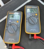
I thought I’d post an update. I received the warranty replacement voltage regulator and was able to reinstall it yesterday. I’ve since had three flights that were all satisfactory. This morning I decided to confirm the voltage readings on my engine monitor versus voltage taken directly from my battery. The left multimeter is reading from a TCW backup battery and the right meter is from the primary battery. The engine monitor pic shows consistency with the meter so I feel good about the new regulator fixing the problem.

Thanks again for all the suggestions.

IMG_5994.jpg
IMG_5993.jpg
 
Low-ohm measurement

Just to emphasize what's already been mentioned. When measuring resistance below 10 ohms common multimeters are not accurate, much more so when measuring less than 1 ohm. Try connecting the two test probes together and see what the meter shows.

Much better way is to measure voltage drop over the path in question. Forget measuring relative to ground. For example, one probe on battery + pole and other probe on field wire input at the alternator -- of course with master and alt field breaker/fuse ON with current flowing through the path and producing voltage drop.

Finn
 
Back
Top