Van's Air Force

The definitive Van's Aircraft support community! Buying, building or flying an RV? Join our exclusive family of mentors and enthusiasts!

Over-voltage protection/alternator failure

FinnFlyer

Well Known Member
I lost electrical power resulting in a forced landing and substantial damage to my RV-4 as mentioned in this post: https://vansairforce.net/threads/battery-failure.232014/ due to battery failure.

As mentioned, I had considered the battery as backup for the alternator and the alternator the backup for the battery. But that didn't work for me when battery failed open.

I had pulled back on the throttle from about 5,000 RPM down to about 4,000 RPM (which should be roughly 8,000 alternator RPM -- still plenty to produce full voltage) and ran for at least 20 seconds at that before the failure. So RPM reduction was not the direct trigger of the failure, although fairly rapid decent (3,700 to 2,700) did cause temperature change under the cowling: 190F to 170F alternator output air.

I removed the alternator and tried to bench test it with a 1/2HP drill motor. It does deliver 12 amps into a 1 ohm test load. 12V from battery is needed to the "field" terminal when first spinning up the alternator, but can be removed once the alternator is outputting about 6V, or so. With battery disconnected there is considerable ripple on the B+ alternator output.

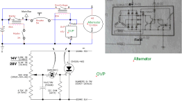
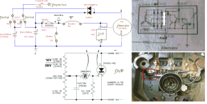
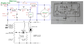
Looking at the attached (abbreviated) schematic you can see that there is a relay between the alternator B+ and the battery. The purpose of the relay is over-voltage protection. If the transistor in the alternator ever shorts to ground, the field winding in the alternator will get full battery/alternator voltage and the alternator will potentially output 100's of volts -- hopefully somewhat shorted to ground by the battery, but could take out all electronics, including the engine controller. The OVP module shorts relay power to ground if voltage exceeds a set point (about 16V). This will then trip the 5A breaker that supplies voltage to the over-voltage relay. It's then up to the battery to supply needed electrical power for the engine to run.

In my case the 5A breaker did not trip! So why did the alternator stop delivering power? We can speculate that the alternator and/or voltage regulator temporarily failed due to heat. However, another possibility is that the OVP circuit did trigger on the spikes from the alternator after the battery failed open and the relay lost power faster than the circuit breaker could trip. With voltage to alternator regulator and field winding being pulled to ground and no voltage from battery to re-energize the relay, the alternator would no longer produce power.

A diode between the breaker and alternator field terminal would have allowed the alternator to continue producing power (output from the three small diodes in the alternator not pulled to ground by the OVP module would have allowed the alternator to produce power and then re-energized the OVP relay. The OVP module might have continued to trigger but alternator would have continued to produce power -- even if very noisy due to no battery filtering -- perhaps too noisy for the engine controller to operate?

So I still recommend a backup battery, as described in the referenced thread, even if you have two alternators!

I may continue to bench test the alternator (heating it with a heat gun) and will post here with any results.
 

Attachments

  • Battery-Alternator.png
    Battery-Alternator.png
    57.4 KB · Views: 161
@FinnFlyer , glad you are OK and thanks for sharing the tech info, particularly for those of us building with electrically dependent engines!

I am wondering in the event of a main battery(or master contactor) failure, has anyone tested if an avionics backup battery being charged through a diode would help stabilize this alternator ripple? I'm still just mid-build, but I will now be very curious to scope the master bus with the main battery offline.
 
In my case the 5A breaker did not trip! So why did the alternator stop delivering power? We can speculate that the alternator and/or voltage regulator temporarily failed due to heat. However, another possibility is that the OVP circuit did trigger on the spikes from the alternator after the battery failed open and the relay lost power faster than the circuit breaker could trip

That would be my bet.

Why does the system include an overvoltage relay in the B-lead? I was under the impression a B-lead relay was only needed for a generating system which could not be shut down by removing field current. Put another way, an OV system can either stop the generation, or or stop the output. Here I see both.
 
I used to run dual caps on the bus for just this reason, inadvertent battery disconnects.
I may put them back in now even though I run std FI and a mag.
Modern capacitors are extremely reliable, especially if not exposed to heat.
The B&C units allow for testing the OV crowbar, it works flawlessly, relay in the B lead is a poor substitute.

1735653813535.jpeg
 
Last edited:
That would be my bet.

Why does the system include an overvoltage relay in the B-lead? I was under the impression a B-lead relay was only needed for a generating system which could not be shut down by removing field current. Put another way, an OV system can either stop the generation, or or stop the output. Here I see both.
I thought I had explained that. If the output transistor in the voltage regulator shorts it will pull the field winding to ground. That would be 12V+ across the field winding. I have never tried it but read that could produce 100V+ alternator output. With an internally regulated alternator there is no way to cut the voltage to the field winding. In my alternator there are two bridge rectifiers in an alternator. The big one goes to B+. The small one goes to the positive side of the field winding and to the voltage regulator.

I originally had disconnected the small rectifier from field winding and internal regulator and had an 80A diode (STPS16045TV) from B+ to battery instead of the relay (to protect battery in case of alternator short). I supplied voltage to the field and voltage regulator via master relay and 5A breaker and OVP module. I had several instances of the breaker tripping when reducing RPM to about 2,000 or lower for landing. So decided to replace the diode with the relay when restoring the internal connection in the alternator. However, still saw at least one instance of breaker tripping and been wondering about that. Could well have been intermittent battery open failure, now that I know about that.

In trying to determine what caused the breaker to trip, I actually had an Arduino Nano box monitoring and logging voltage excursions on the 5A breaker, sampling at 120uS rate. Unfortunately it was flushing collected data array to SD card as the event happened. (The box was powered independently by a small 6V battery.)

In retrospect, my original configuration was probably superior (other than having to take a replacement alternator apart to remove that connection).

Internal battery disconnect was a failure mode I had not considered.
 
I used to run dual caps on the bus for just this reason, inadvertent battery disconnects.
I may put them back in now even though I run std FI and a mag.
Modern capacitors are extremely reliable, especially if not exposed to heat.
The B&C units allow for testing the OV crowbar, it works flawlessly, relay in the B lead is a poor substitute.
Interesting that you should mention that. I had had a 22,000uF 16V cap on the engine bus (always connected to battery via fusible link) in attempt to reduce noise on the bus. Unfortunately I had removed that, not being comfortable with it in the cockpit.
Completely agree about relay in B+ lead. See http://forums.matronics.com/viewtopic.php?p=514422#514422
However, for an alternator with internal regulator (that cannot be disconnected) the relay is needed.
 
Last edited:
Very interesting.

I am running the full SDS system with electric pumps and EFI, and a full glass panel as well - so electrically dependent for both power and nav. Single battery, dual alternator. My primary alternator is on the standard Cessna style split-master, and it's my habit in flight to occasionally turn on my standby alternator and turn off my primary alternator via that split bus to exercise the backup alternator and keep an eye on its function. Three times in turbulence I have managed to shut down the BATT side of the split master when trying to turn off just the ALT side, resulting in opening my master switch and removing the battery from the system, with the backup alternator functioning. In each case the airplane continued to function normally - no engine stoppage, no grey-outs.

I pulled the user logs after the first incident and reviewed my voltage data - it definitely moved around a bit more than usual when the battery was offline, but only about 1/2 a volt around the setpoint. The total electrical load was around 20 amps, so enough to put a decent load on the alternator and have the regulator pretty much in the middle of its control range, which is where they tend to do the best. In my case the electrical loads are pretty much constant (pumps, ignition, full panel) and both stable and substantial - best case scenario for an alternator without a battery to absorb the bumps. Any significant changes in load would result in voltage excursions up or down faster than the regulator can react, and either result in the output voltage falling below the level where the regulator can recover, or rising to the point of the OVP tripping. I have not tested this configuration with variable loads like lighting, or radio transmission - it's quite possible that would be enough to hit the limits. I'm liking Walt's idea of the capacitors on the system but I'm questioning the large charge current on initial connection, and whether that may cause arcing on the master solenoid when you bring it online.

I have no doubt that, had I reduced RPM significantly at that point, the voltage would have sagged below recovery, just as it did with the OP.
 
Last edited:
I used to run dual caps on the bus for just this reason, inadvertent battery disconnects.
I may put them back in now even though I run std FI and a mag.
Modern capacitors are extremely reliable, especially if not exposed to heat.
The B&C units allow for testing the OV crowbar, it works flawlessly, relay in the B lead is a poor substitute.
I'm curious. Have you tested it with the caps and battery disconnected?

My alternator actually has a (small) cap in it but with a load on the alternator (6 to 12 amps) it does nothing to the ripple and it appears that the internal voltage regulator uses average rather than peak values when regulating. That means you can easily have ripple peaks above 15V. The regulator in my alternator is a VR199. The alternator schematic I posted is from an old Haynes Mazda RX-7 manual. Who knows what's inside a modern VR199? Bench testing the alternator I see some high frequency spikes on the o'scope. No clue if they're from noise from the brushes.
 
I'm curious. Have you tested it with the caps and battery disconnected?
Yes I did, and the B&C continued to supply power with no obvious issues.
Caps on alternators (or inside) are for high freq noise suppression, not DC smoothing.
 
Walt, can you recommend a high quality (reliable) DPDT 15 to 20A switch?

(I guess if I anyway have to have a switch in the line from battery(ies) to engine bus, I might as well have an On-Off-On DPDT if available.)

I really prefer using a switch rather than a relay.
 
Very interesting.

I am running the full SDS system with electric pumps and EFI, and a full glass panel as well - so electrically dependent for both power and nav. Single battery, dual alternator.
Single battery with dual (or more) alternators is not what I consider adequate for an electrically dependent engine.

I suggest two identical ship batteries, where one has enough reserve capacity to run the plane for 1 to 2 hours (the limiting design case). The engine load connects to the batteries before the master relays.

The two identical ship batteries provide for easy care and feeding (as compared to adding a plethora of backup batteries). This supports some confidence in electrical power reserve. I have found dead backup batteries in RVs with electrically dependent engines.

Carl
 
Very interesting.

I am running the full SDS system with electric pumps and EFI, and a full glass panel as well - so electrically dependent for both power and nav. Single battery, dual alternator.
...
I pulled the user logs after the first incident and reviewed my voltage data - it definitely moved around a bit more than usual when the battery was offline, but only about 1/2 a volt around the setpoint. The total electrical load was around 20 amps...
Good datapoint. Can you share if you have any sort of a (avionics)battery soaking up power as part of that "full glass panel"?
 
Single battery with dual (or more) alternators is not what I consider adequate for an electrically dependent engine.

I suggest two identical ship batteries, where one has enough reserve capacity to run the plane for 1 to 2 hours (the limiting design case). The engine load connects to the batteries before the master relays.

The two identical ship batteries provide for easy care and feeding (as compared to adding a plethora of backup batteries). This supports some confidence in electrical power reserve. I have found dead backup batteries in RVs with electrically dependent engines.

Carl
Would you consider diodes more reliable than a switch in connecting the batteries to the engine bus (assuming that overvoltage on each battery is properly prevented)?
 
Would you consider diodes more reliable than a switch in connecting the batteries to the engine bus (assuming that overvoltage on each battery is properly prevented)?
No. You still need a switch anyway between each battery and the engine, and how you do these switches allows for various backup modes.

Carl
 

Where is the wire labeled A-02 in your alternator schematic get connected to your circuit?
Unfortunately there are two wires labeled as such in that copied schematic. The top one (the one with a diode) is not connected to anything in my circuit. The bottom one is basically the field voltage. Needs 6 to 12V to get alternator producing power, after which it can be disconnected. Do remember that that schematic may or may not be correct for the VR199 internal voltage regulator. But the terminal I labeled "field" definitely goes to the output of the small rectifier bridge and to the positive side of the field winding.

During my bench testing the alternator did start to output power after connecting a 12V battery to the upper A-02 and running it for some seconds. 8V ripple and measured 17.3V peak on B+ at relatively low RPMs (1,000?) with 1.1 ohm load.

So many unknowns. Would love to get a current schematic of modern VR199 voltage regulators.

Actually I've even considered making my own external voltage regulator so I know exactly how it works. The issue would be to get access to both brushes to field winding and disable internal regulator.
 
Walt, can you recommend a high quality (reliable) DPDT 15 to 20A switch?

(I guess if I anyway have to have a switch in the line from battery(ies) to engine bus, I might as well have an On-Off-On DPDT if available.)

I really prefer using a switch rather than a relay.
I always use the Honeywell 1TL or 2TL series, if you want you can use the DPDT 2TL and jumper the terminals together for some added capacity.
 
Unfortunately there are two wires labeled as such in that copied schematic. The top one (the one with a diode) is not connected to anything in my circuit. The bottom one is basically the field voltage. Needs 6 to 12V to get alternator producing power, after which it can be disconnected. Do remember that that schematic may or may not be correct for the VR199 internal voltage regulator. But the terminal I labeled "field" definitely goes to the output of the small rectifier bridge and to the positive side of the field winding.

During my bench testing the alternator did start to output power after connecting a 12V battery to the upper A-02 and running it for some seconds. 8V ripple and measured 17.3V peak on B+ at relatively low RPMs (1,000?) with 1.1 ohm load.

So many unknowns. Would love to get a current schematic of modern VR199 voltage regulators.

Actually I've even considered making my own external voltage regulator so I know exactly how it works. The issue would be to get access to both brushes to field winding and disable internal regulator.

The voltage regulator needs to have a connection to the bus voltage. It is called the sense voltage and sometimes labeled the “S”. I’m pretty sure in that circuit A-02 is the sense input.
 
The voltage regulator needs to have a connection to the bus voltage. It is called the sense voltage and sometimes labeled the “S”. I’m pretty sure in that circuit A-02 is the sense input.
Actually in the car schematics the lower A-02 goes to alternator warning relay coil and ignition via diode. The upper A-02 directly to ignition. So, yes the upper is probably sense (but can also -- more slowly -- supply voltage to field for startup). The alternator warning relay coil should also supply some startup power to the field. No idea what the alternator warning relay coil resistance is. In my configuration it looks like either works. Disadvantage of powering lower A-02 is it draws 3.25A until alternator is spinning whereas the upper A-02 only draws 0.27A and would not reverse-feed (charge) the battery thru small rectifier bridge when alternator is up to speed, unlike the lower A-02. However, when cutting the internal connection between small rectifier bridge and field/regulator I do need to power the field externally via the lower A-02. I guess in that case I could still connect the upper A-02 to battery for more accurate voltage output?
 
...

Good datapoint. Can you share if you have any sort of a (avionics)battery soaking up power as part of that "full glass panel"?
I have a backup battery in the Dynon Skyview, but it stays charged and was just along for the ride. No other "backup" batteries.
 
Not sure if this would be an appropriate question for this thread but I have an automotive alternator converter to use a B&C external regulator LR3D which includes overvoltage protection. If my battery fails am I to understand that the alternator may spike resulting in the regulator taking the alternator offline producing no voltage thereafter.

I have dual Pmags with internal alternators which continue to operate independently as long as RPMs remain over the minimum required for internal power but it is important to know if this type setup may result in a total loss of electrical power in the event of a battery failure.
 
I used to run dual caps on the bus for just this reason, inadvertent battery disconnects.
I may put them back in now even though I run std FI and a mag.
Modern capacitors are extremely reliable, especially if not exposed to heat.
The B&C units allow for testing the OV crowbar, it works flawlessly, relay in the B lead is a poor substitute.

View attachment 77369
I also use a large capacitor to smooth out spikes in the event of battery failure. also maybe helps with alternator noise in the headsets. Nice looking installation you have!
 
I thought I had explained that...

Ahhh, so you did, sorry. Ok, a self excited, internally regulated alternator.

Internal battery disconnect was a failure mode I had not considered.

It's just a battery disconnect. Doesn't matter if it's internal, or a corroded post, or a bad cable crimp. All are common in automobiles, but don't typically take the alternator off line. Here the added OV module did the deed. Where was it sourced?
 
if the ovm opens the relay on the b lead because of a loss of power caused by a bad battery , shouldn't the alternator supply that power and keep the relay closed?
 
Wired per this diagram, it looks like the OV module grounds the field.

Battery-Alternator.png
 
if the ovm opens the relay on the b lead because of a loss of power caused by a bad battery , shouldn't the alternator supply that power and keep the relay closed?
Well, if the alternator produces overvoltage you do want the relay to release -- but otherwise it should. Just bad design on my part.
Wired per this diagram, it looks like the OV module grounds the field.
You are exactly right, Dan. A diode in that path may have saved the day. Or (as I discovered by bench test) power the field for startup through the upper "A-02" connector. Takes a second or two for field to build up and the alternator to start outputting power. Also only draws 0.27A instead of 3.2A with alternator not running.
However the ripple from the alternator with no battery may keep activating the OVP. Something I need to bench test.

BTW, my alternator is not self-exciting. Does need external power to start (build up sufficient field to then start providing power via the three small diodes to the field winding). So, more like self-sustaining. So if field voltage momentarily pulled to zero there may not be enough residual magnetic field to get it producing power again.

Everything points to the need of a backup battery or at the very least big capacitors to smooth out the ripple -- that is if you want over voltage protection.
 
Last edited:
BTW, my alternator is not self-exciting. Does need external power to start...

Yes, poor wording on my part. It's a classic, straight from the old Bosch Automotive Electrical Manual. Pretty sure the input you have marked as "field" was intended for the dashboard charge warning light.

Everything points to the need of a backup battery or at the very least big capacitors to smooth out the ripple -- that is if you want over voltage protection.

I'd want the backup battery regardless.

So again, where did the "OVP" come from?
 
Last edited:
Yes, poor wording on my part. It's a classic, straight from the old Bosch Automotive Electrical Manual. Pretty sure the input you have marked as "field" was intended for the dashboard charge warning light.
Again you're spot on. Checking the Haynes Mazda RX-7 car manual, the one I marked "Field" goes to one side of Alternator Warning relay coil (the other side of coil to ignition switch). Even though alternator powers on more slowly, I should have used the upper "A-02" terminal (which goes directly to the ignition switch in the car).
In any case I think I'm going to revert to my original configuration: unsolder the connection from the three small diodes to the voltage regulator and supply voltage to the field and internal voltage regulator and power field and voltage regulator externally (from 5A breaker and OVP module). And replace the relay with a diode.
I'd want the backup battery regardless.
Definitely!
There have been suggestions of being able to use both batteries for extended flight time after alternator failure, using multiple switches and/or diodes, but now I think that just a simple DPDT switch to select battery for engine bus (and charging backup battery via diode to alternator when in normal mode) would allow that too: When the main battery starts going low, just switch the engine bus to the backup battery. Considering the cost of very high quality switches, I think I'll go with a reasonably priced SPDT switch, and an SPST switch from backup battery to engine bus for switch redundancy. Obviously I'll have my engine monitor showing both battery voltages.
If I can't find a suitable airport in one to two hours I don't need to be flying.
So again, where did the "OVP" come from?
AeroElectric, Bob Nuckolls. Attached. There are later versions due to the MBS4991 no longer being sold. But I happened to have some on hand from decades ago.
Newer:
 

Attachments

Last edited:
... think I'm going to revert to my original configuration: unsolder the connection from the three small diodes to the voltage regulator and supply voltage to the field and internal voltage regulator and power field and voltage regulator externally (from 5A breaker and OVP module).

Do you have a lot of expensive avionics? If not, consider...you're flying a Mazda, and it was pretty reliable as a Mazda. Maybe it would be best to just keep it as Mazda as possible. No alternator mods, no OVP module. Reality says the OVP addition put your airplane in the dirt.

Forty years in the car business, recon and repair, thousands of units. I don't recall ever seeing an overvoltage take out an OEM ignition.

And replace the relay with a diode.

I don't have a Mazda manual handy, but typical OEM wiring would place a fusible link near the battery post to protect against a shorted B-lead. The fancy equivalent would be an ANL. Both are durable. A diode near the primary battery post would offer the same protection, but with some charge voltage drop.

Using a diode to charge the backup battery is common enough. You mentioned using the engine monitor to to show both battery voltages. Note your real interest is battery voltage under ignition load with no alternator input.
 
Do you have a lot of expensive avionics? If not, consider...you're flying a Mazda, and it was pretty reliable as a Mazda. Maybe it would be best to just keep it as Mazda as possible. No alternator mods, no OVP module. Reality says the OVP addition put your airplane in the dirt.
My first thought or reason for OVP was to protect avionics (D-100 and 1090ESG) and hadn't given any thought to the engine controller, etc.
Forty years in the car business, recon and repair, thousands of units. I don't recall ever seeing an overvoltage take out an OEM ignition.
But I'm not using OEM controller. Just now I looked up the specs for the UA7805CKC 5V regulators in my RWS EC3. 35V absolute max input voltage (25V max recommended). They are preceded by a 22uH choke and 1,000uF 25V cap. I'm not sure what happens to an electrolytic cap when exposed to short duration spikes beyond the 25V voltage. But it should be safe to operate the EC3 up to 25V. Thus it should be safe to raise the OVP trigger point to 20V or more given its 2.5Kx10uF ~ 20mS averaging filter.

I don't know what car OEM controllers are spec'd to.

Years ago I was making a living fixing computer monitors. Typically the high-voltage transformer transistor would fail. Bummer is I don't remember if it failed open or shorted. The transistor (could be a power-FET these days, who knows?) controlling the field winding in the alternator failing shorted is really my only concern. Would be really, really nice to know how often (if ever) that happens. If it's never happened in the millions of vehicles out there then there's a good reason to remove the OVP crowbar. Why was OVP protection introduced in the first place?
I don't have a Mazda manual handy, but typical OEM wiring would place a fusible link near the battery post to protect against a shorted B-lead. The fancy equivalent would be an ANL. Both are durable. A diode near the primary battery post would offer the same protection, but with some charge voltage drop.
Not concerned about the drop over the diode. The internal voltage regulator overcomes that because it's looking at the voltage supplied to the field winding.
Using a diode to charge the backup battery is common enough. You mentioned using the engine monitor to to show both battery voltages. Note your real interest is battery voltage under ignition load with no alternator input.
Yep. Will change engine monitor to monitor both and with alarms on both.

I also looked into putting a cap on the B+ lead. By putting the cap on the B+ lead I wouldn't be loading any switch or relay points with sudden inrush current. About 10A current draw on the engine bus. Not quite sure of frequency on alternator output, but if one sine per coil (three coils) per rotation I get: Low engine idle 1,500 RPM, alternator 3,000 RPM gives 3000 / 60 * 3 * 2 (bridge rectifier) ~ 300 Hz. C = I / (f x Vpp) = 10 / (300 x 1) ~ 30,000uF capacitor. I think that 1V ripple would be more than acceptable and unlikely to trip OVP if set to 20V. 14.8V (max alternator output voltage -- typically ranges from 14.2 to 14.5) + 0.7V (diode) + 0.5V (half ripple) = 16V. If I go that route I will definitely do ground testing with an o'scope, varying RPM, activating flaps, lights, etc.
$10-20 for a capacitor to ensure usable alternator power in case of battery open failure would be cheap insurance. Life of capacitor is in question. Would need to be checked at least annually. So would I still need a backup battery? How likely is a battery short? Alternator B+ short is handled by the diode (although not sure 45V is enough). I originally considered the STPS16045 diodes as a likely fusible link.

Edit: Referring to but forgot I hadn't posted my proposed new system here. Now attached. The added picture is how one can disconnect the internal voltage regulator from internal supply via three rectifying diodes, thus making alternator dependant on externally supplied voltage (basically an external voltage regulator set-up). The tab in the red square is normally bent down and solderted to the rectifier bridge assembly.
 

Attachments

  • Battery-Alternator-Better.png
    Battery-Alternator-Better.png
    95 KB · Views: 19
Last edited:
My first thought or reason for OVP was to protect avionics (D-100 and 1090ESG) and haven't given any thought to the engine controller, etc.

But I'm not using OEM controller. Just now I looked up the specs for the UA7805CKC 5V regulators in my RWS EC3. 35V absolute max input voltage (25V max recommended). They are preceded by a 22uH choke and 1,000uF 25V cap.

FYI, if your avionics are designed to DO-160 specs, they should be good for (going off the top of my head) at least 32V continuous, with brief excursions to 60V. In an electrically-dependent aircraft, I think I personally would want to look for an ignition system with similar or better overvoltage protection.
 
FYI, if your avionics are designed to DO-160 specs, they should be good for (going off the top of my head) at least 32V continuous, with brief excursions to 60V. In an electrically-dependent aircraft, I think I personally would want to look for an ignition system with similar or better overvoltage protection.
I can probably find 5V regulators that can handle more then 35V input max and I could replace the 1,000uF 25V caps with 50V caps but I'd rather concentrate on ensuring proper power from the alternator.
 
Last edited:
...
Forty years in the car business, recon and repair, thousands of units. I don't recall ever seeing an overvoltage take out an OEM ignition.
...
OK Dan.

I reread Bob's notes on failed alternator regulators: "While the probability of regulator failure in cars is exceedingly low, it is not zero."

Attached is probably what I should have done. (Bob's "Z-24".) Use internal regulator. Keep power to overvoltage relay separate from power to startup/sense terminal on alternator*. Let OVP unit disconnect alternator from battery if overvoltage detected (and let alternator destroy itself in case of real alternator runaway). Ability to monitor voltage on B+ so can reset 5A breaker in case of nuisance trip (alternator would continue producing voltage and not need startup power). The 30,000uF capacitor on B+ terminal should provide reasonable clean (low ripple and noise) voltage from the alternator in case of failed open battery. Maybe add back the diode in series with the overvoltage relay in case of alternator B+ short to ground? (Could be handled by pulling the 5A breaker but not automatic.) Or fusible link or ANL fuse as suggested.

Simultaneous battery and alternator failure should be very rare, but still not a bad idea to add backup battery as previously shown.

Edit: * Actually with the overvoltage relay (and big capacitor on B+) in place, there is no reason why the Start/sense cannot be connected directly to the B+ terminal. In normal operation the overvoltage relay would close when master switch/relay is turned on and connect battery to B+ (and thus the startup/sense terminal).
There is an error in attached Z-24 diagram (Adapting_IR_...) . It shows the F terminal on the alternator connected to overvoltage relay power -- just like I had!
 

Attachments

Last edited:
Back
Top