My Fix to the Problem
Let me start this post by saying that I make no claims that my approach is better/worse than the original design. I wanted to try something different based upon some research into what others have found and done. (Van's isn't the only one with a lot of experience!!) This design is also based upon a couple of objectives:
1) I'm not moving the voltage regulator inside the cabin. I don't want the unprotected wires inside and if the VR goes TU again, the smell can be quite horrible. Just my preference, you can do what you want. I think this is prudent especially if you believe the arguments that the regulators are failing due to vibration and poor quality construction!
2) I didn't want to undo the original installation. I wanted the ability to go back to the original install if possible. (Don't ask me why, I have no idea. It seemed like a good option to keep open.)
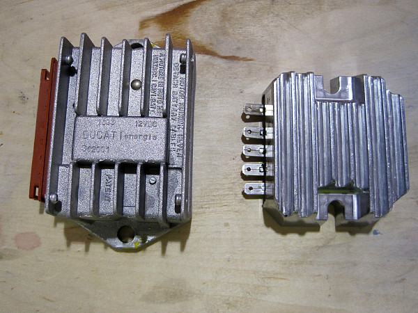
3) The Ducati voltage regulator has a track record of unreliability in aviation installations. It doesn't seem prudent to just throw another one back in. I don't know the reasons why they fail, but the fact that they do fail is undeniable. My new one may fail as well in the same location. At least we'll have a different data point.
4) I wanted to provide an additional data point to the discussion so I am using a different regulator but in the same position (See #2 above).
With that said, here's a picture show of what I did to install a new voltage regulator. Let the flames begin.
Here's a shot of the old and the new. The new part is a voltage regulator for a John Deere garden tractor. You can buy them at NAPA auto parts. The part number is SME 7068102. The Corvair engine folks have been using this regulator for years. This happens to be the newest version of it. Beware of cheap Chinese knock-offs that you can buy on Flea-Bay for $45. There's not much in the way of cooling fins on those. The new one is rated at 20 amps and cost about $89 at NAPA.
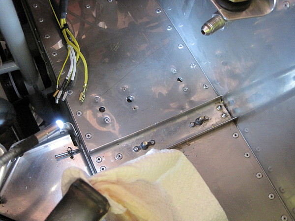
I removed the radiator hose and the fuel pressure hose in order to gain better access to the voltage regulator position. Using a small flat bladed screwdriver, I was able to remove the wires from the Ducati clip without incident. I did not have to modify the wires at all.
Here's the hardest part of the install, putting in a new nutplate and mounting hole for the smaller regulator. The rudder pedals are directly below the hole so it took some trickery to get the nutplate positioned and riveted, but it's doable. It took me about an hour.
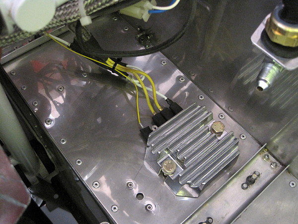
I used some longer -4 bolts from my parts bin to mount the new regulator using the rear hole of the original installation and the new hole I drilled. I also mounted the existing clips to the new regulator using some shrink tubing to provide protection. There is an extra wire left over when using this regulator. The Ducati has two power wires, which is simply the wire from the battery/bus split into two. I just covered it with shrink tubing and tie wrapped it to the wiring bundle. Normally I would install protected wire clips for this type of install, but I wanted to keep the original installation options open so I used heat shrink tubing. It will work just fine. Now all that's left is to design a heat shroud for this installation.
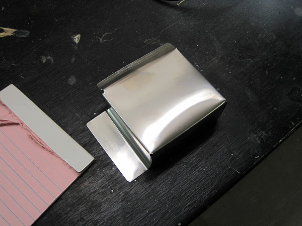
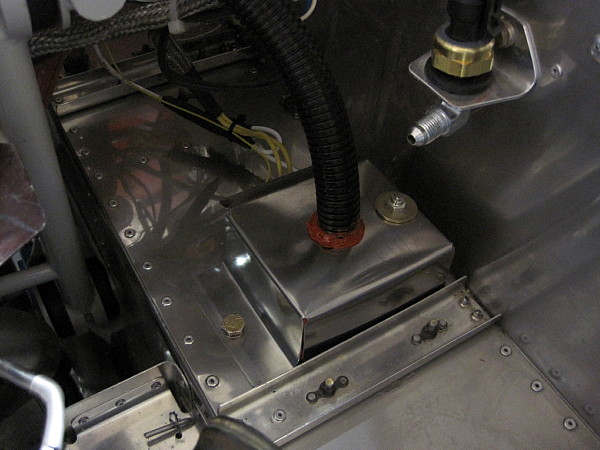
I decided to make a shroud out of stainless steel sheet. I could have used aluminum, I had some stainless and thought it might have better thermal protection qualities. I wanted some space around the regulator so I made the box about 1/4" larger on all sides. The goal was to provide some protection from the flow of hot air out of the radiator and to also capture the cooling air from the plenum. The box is open on the side of the electrical connections but fully encloses the regulator on the other three sides.
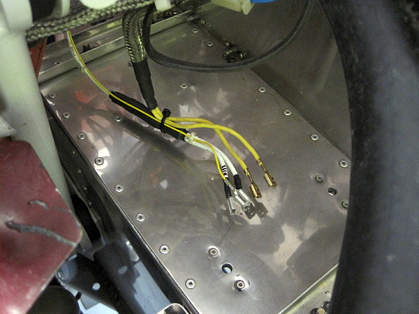
Here's the final install. I used the original front hole to mount the box and designed it to slip underneath the regulator in the back. I really didn't want to installed another nutplate so I designed it this way. It's not the slickest design, but it will work for now. I had to drill a hole in the top to get to the rear bolt of the regulator to tighten it so I covered it with a simple bolt and washer. Oh well, an engineer I'm not.
So that's it. I'm waiting for it to stop snowing so I can test run the engine. Hopefully all the smoke will stay in the wires. The entire change took me about 5 hours to complete. The wiring is unmodified and the original mounting holes are still there. I even used the same cooling tube from the plenum. I simply added one nutplate, three new -4 bolts of different lengths, some heat shrink, and the new shroud and new regulator. Let the testing begin.


")


