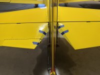
I just landed from doing the flight testing on my new elevator root fairings. These are very light-weight fiberglass fairings that improve the aerodynamics of the area between the elevator and the rudder, taking advantage of extra room, but no change to the gap to the rudder skin from the elevator trailing edge.
Tests were done at 7500 ft pressure alt, 63F OAT, 2400 RPM, 22.5 in Hg. MAP, 8.0 gph fuel flow. Tests both days had almost identical atmosphere (wind, OAT) with less than 5 kt wind, except for the first test with the fairings installed, which had a 19 kt wind. Despite that, the computed TAS from that test was extremely close to the other results - Gives great confidence in the results.
Baseline, no fairings, average of three GPS Speed Triangle tests = 166.6 KTAS
With fairings, average of four GPS Speed Triangle tests = 168.2 KTAS.
So it looks like the fairings are good for 1.6 kts.
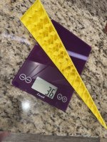
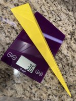
Here's a couple of pictures. It is hard to descern the contour shape from the pictures - I will draw some stream lines on one and take another picture so you can see the gentle curve to a trailing edge provided by the fairing.


Tests were done at 7500 ft pressure alt, 63F OAT, 2400 RPM, 22.5 in Hg. MAP, 8.0 gph fuel flow. Tests both days had almost identical atmosphere (wind, OAT) with less than 5 kt wind, except for the first test with the fairings installed, which had a 19 kt wind. Despite that, the computed TAS from that test was extremely close to the other results - Gives great confidence in the results.
Baseline, no fairings, average of three GPS Speed Triangle tests = 166.6 KTAS
With fairings, average of four GPS Speed Triangle tests = 168.2 KTAS.
So it looks like the fairings are good for 1.6 kts.
Here's a couple of pictures. It is hard to descern the contour shape from the pictures - I will draw some stream lines on one and take another picture so you can see the gentle curve to a trailing edge provided by the fairing.
")