

goatflieg
Well Known Member
There have been a lot of creative solutions shared here on how to rotate your wings during the painting process. I've borrowed some ideas from different sources and come up with my own "wing rotation jig system". It's eyeball-engineered so I won't quote specifications here. Instead I will present this slideshow in hopes it might inspire someone to make their own simple, low-cost solution.
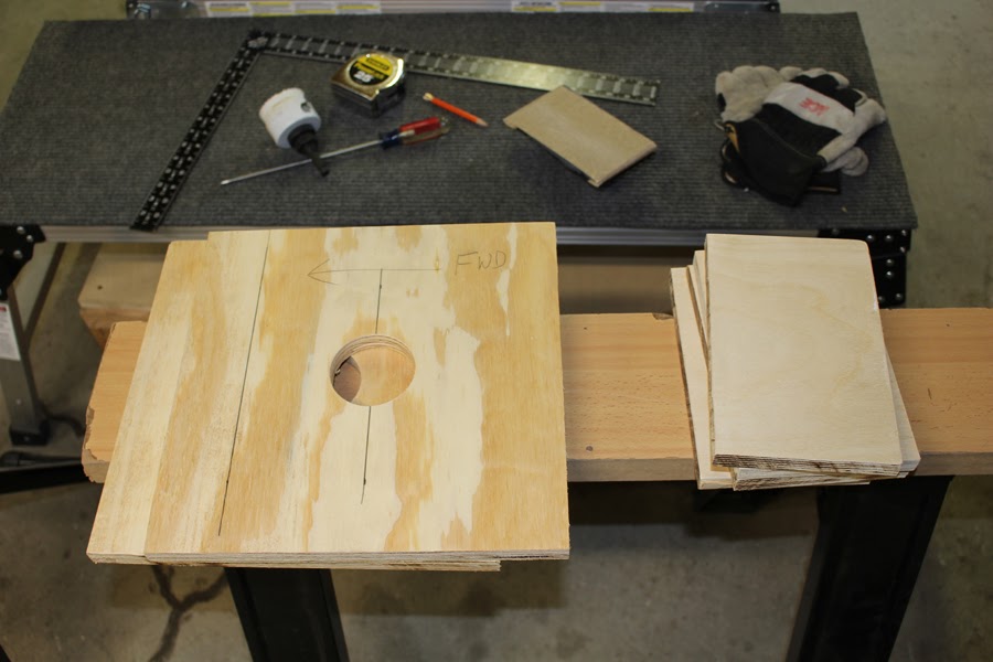
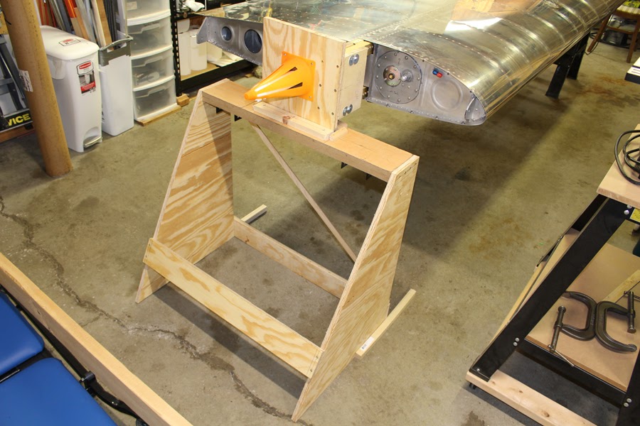
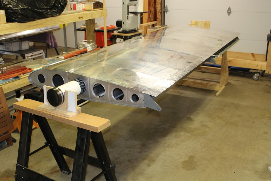
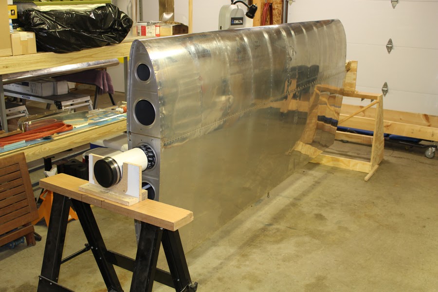
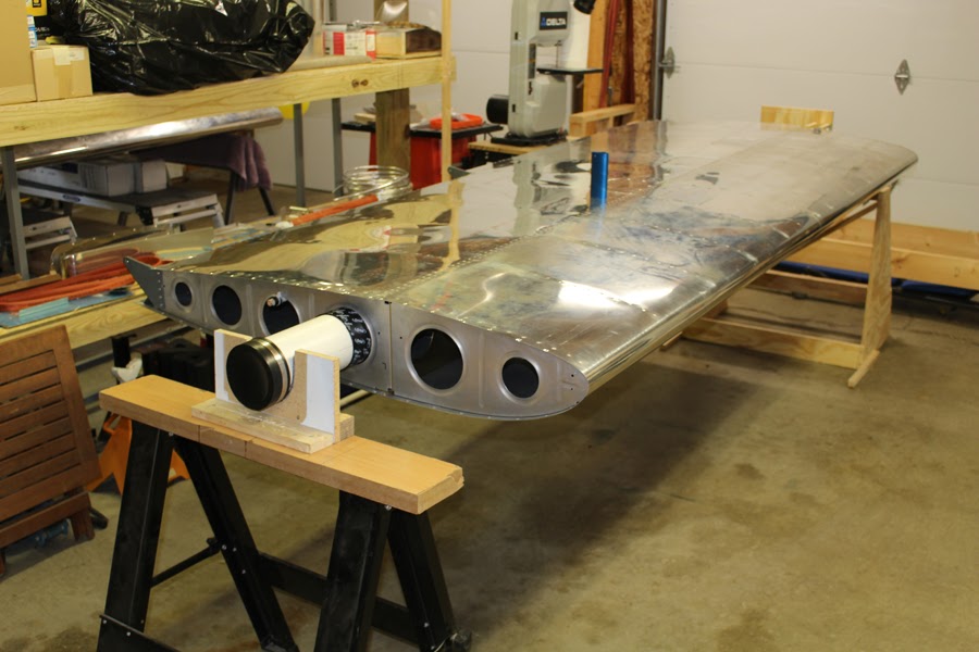
I had considered assembling a proper rotisserie that was tied together at both ends and utilized an engine stand as a pivot point, but that seemed too complicated and expensive to do properly. I liked the simplicity of the square solution that I originally saw in the TV series "From The Ground Up". I wasn't about to weld up any metal fixtures like Joe Schumacher did, but I've seen others use the "square-on-spar" method and designed my own. I had some heavy plywood scraps available, so I used it to fabricate most of the components. I've also seen 4" PVC pipe used as a pivot point for the outboard end and that seemed like a simple and efficient way to do it. Knowing that the center of gravity is aft of the spar, the box was mounted so the center of rotation would line up with the rib holes just behind the spar, and it worked out well. You'll note that I chose to work around the installed aileron pushrod; it was torqued and sealed and I wanted to keep it that way.
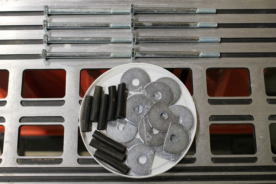
I used 1/4" bolts and cut nylon hose sections to serve as shims that would protect the spar holes. I wanted the extra surface area of fender washers, but they needed to be trimmed to avoid overlap.
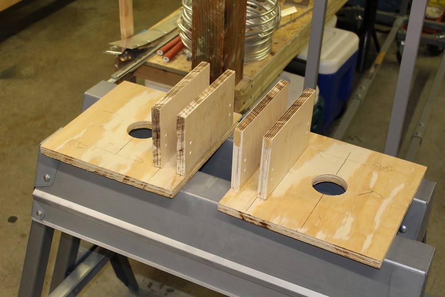
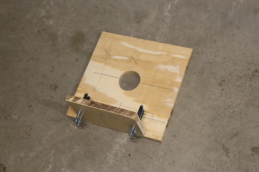
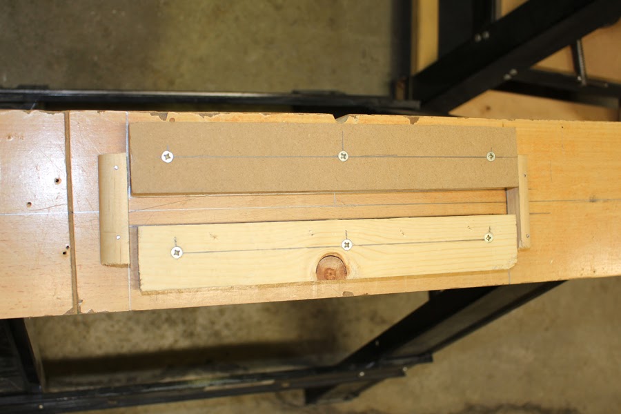
The forward clamping board was glued and screwed onto the pivot square; the aft clamping board was only screwed to the pivot square using long screws and bolted to the spar and forward clamping board. This made it easy to remove for disassembly. I considered adding some angle as additional reinforcement but it doesn't seem to be necessary.
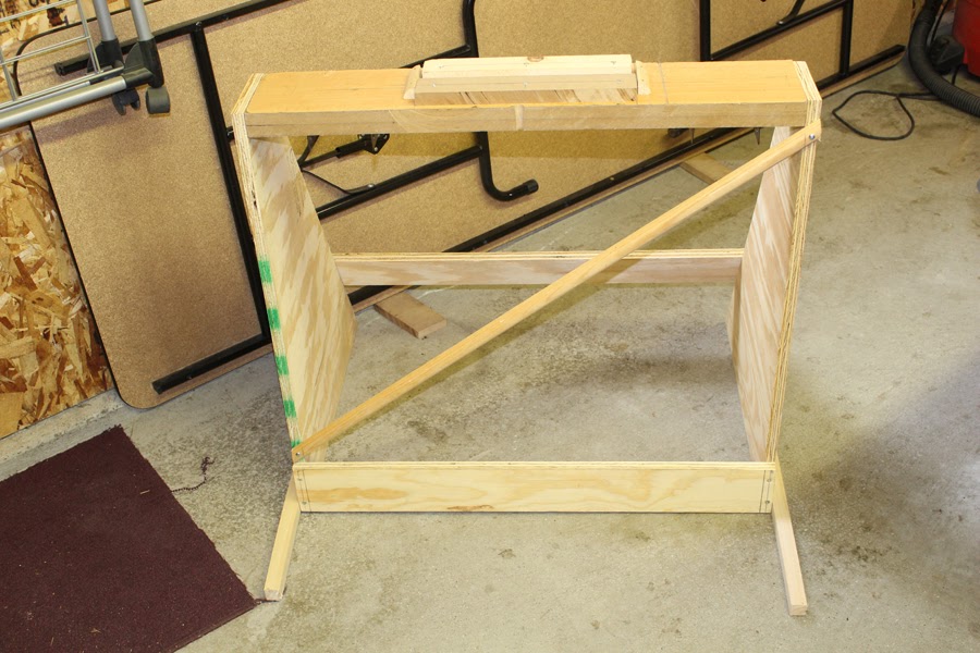
Using a sawhorse I had on hand, I attached cleats that would hold the square firmly in place.
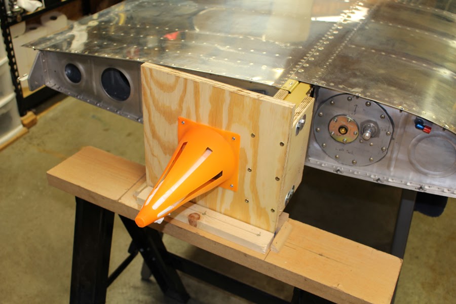
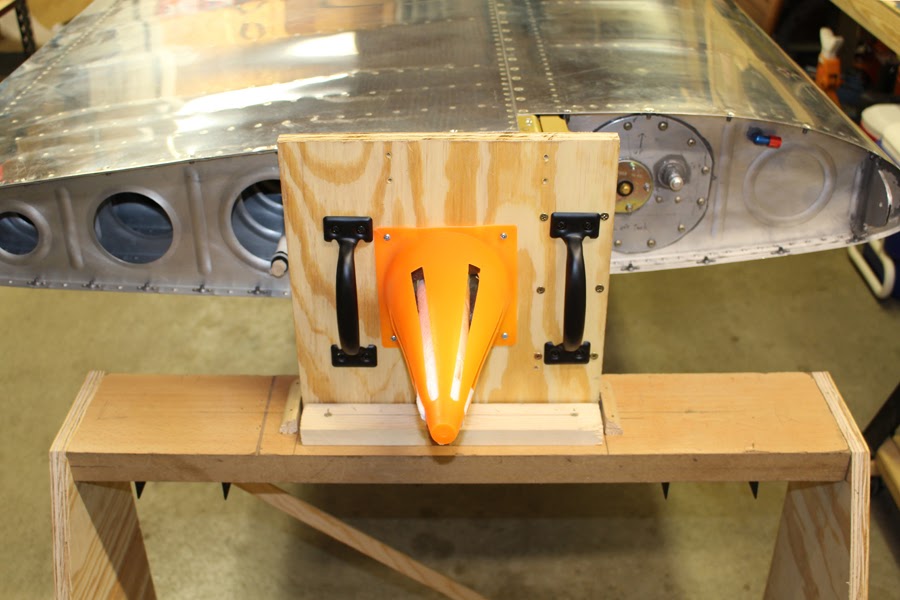
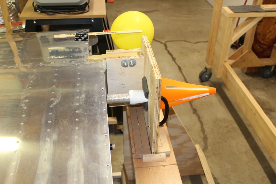
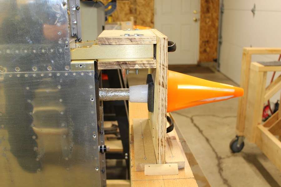
I wrapped and padded the aileron pushrod and used a small traffic cone as a guard.
I had set up both ends on a matching set of sawhorses. I had adapted the outboard end so that I had swinging room, but on the spar end I realized that the sawhorse legs would interfere with wing rotation. Since I had the wing height set and level and wanted to keep it that way, I decided to fabricate new support ends around the existing sawhorse beam, building around the legs before removing them. Fiddly... but it worked.
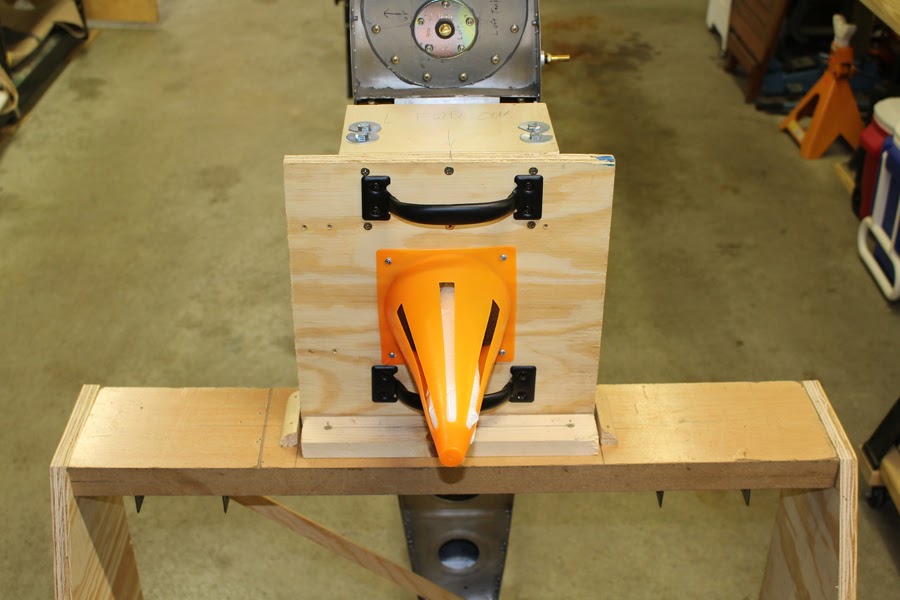
After testing, I decided handles would be a good idea. I initially placed them incorrectly and had to make adjustments so that they wouldn't interfere with the positioning cleats. Care had to be taken when screwing the handles to the squares; some screws were shortened so as not to contact the ends of the spars.
I had considered assembling a proper rotisserie that was tied together at both ends and utilized an engine stand as a pivot point, but that seemed too complicated and expensive to do properly. I liked the simplicity of the square solution that I originally saw in the TV series "From The Ground Up". I wasn't about to weld up any metal fixtures like Joe Schumacher did, but I've seen others use the "square-on-spar" method and designed my own. I had some heavy plywood scraps available, so I used it to fabricate most of the components. I've also seen 4" PVC pipe used as a pivot point for the outboard end and that seemed like a simple and efficient way to do it. Knowing that the center of gravity is aft of the spar, the box was mounted so the center of rotation would line up with the rib holes just behind the spar, and it worked out well. You'll note that I chose to work around the installed aileron pushrod; it was torqued and sealed and I wanted to keep it that way.
I used 1/4" bolts and cut nylon hose sections to serve as shims that would protect the spar holes. I wanted the extra surface area of fender washers, but they needed to be trimmed to avoid overlap.
The forward clamping board was glued and screwed onto the pivot square; the aft clamping board was only screwed to the pivot square using long screws and bolted to the spar and forward clamping board. This made it easy to remove for disassembly. I considered adding some angle as additional reinforcement but it doesn't seem to be necessary.
Using a sawhorse I had on hand, I attached cleats that would hold the square firmly in place.
I wrapped and padded the aileron pushrod and used a small traffic cone as a guard.
I had set up both ends on a matching set of sawhorses. I had adapted the outboard end so that I had swinging room, but on the spar end I realized that the sawhorse legs would interfere with wing rotation. Since I had the wing height set and level and wanted to keep it that way, I decided to fabricate new support ends around the existing sawhorse beam, building around the legs before removing them. Fiddly... but it worked.
After testing, I decided handles would be a good idea. I initially placed them incorrectly and had to make adjustments so that they wouldn't interfere with the positioning cleats. Care had to be taken when screwing the handles to the squares; some screws were shortened so as not to contact the ends of the spars.
")

