Norman CYYJ
Well Known Member
A new way to control the plane if the joy stick jams, lolThen you will be able to adjust your indicated airspeed and altitude by opening and closing cabin vents.
I've done these tests!


A new way to control the plane if the joy stick jams, lolThen you will be able to adjust your indicated airspeed and altitude by opening and closing cabin vents.
I've done these tests!
If you have a Skyview...Yes, you did that wrong. Try it again with the spreadsheet.
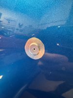
When trying to determine the most favourable position to place a static port, designers attempt to locate a point on the airframe where the local pressure is invariant with respect to pitch and close to a Cp of 0 (So freestream velocity). They can guesstimate this using CFD and running the model through different alphas. When they plot the pressure variation on the fuselage, they can pinpoint an area where the lines at Cp==0 cross at different alphas. That's the sweet spot. Yaw is taken care of by installing two ports on each side to try to average out the yaw effect.Here’s a close-up. The static ports are smallish- maybe the size of a nickel.
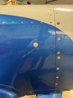
Below is where they sit on the plane.
I can't help you on location, but I have those ports and like them. Solved my problem.Using these ports from Showplanes: https://showplanes.com/Item/SP-01
The’re supposed to have the same profile as the Van’s pop rivet design, and should be a very straightforward installation.
Worked great on mine, it's like a pop rivet with a barb.Thanks to all who’ve responded so far.
I’ve decided to relocate my static ports to the aft fuselage,
Using these ports from Showplanes: https://showplanes.com/Item/SP-01
The’re supposed to have the same profile as the Van’s pop rivet design, and should be a very straightforward installation.
Now- can I get some help on exactly where to put them in the aft fuselage?
How far forward of which bulkhead, and how far above which stringer?
This is for my F-1 Rocket, so measurements from a Rocket or an RV-4 would be the most helpful.
Thanks! That's just the information I needed.Edit: the OP of the link below initially had the same forward port location with the exact error you are reporting.
See post #’s 2 and 4 for the new location of your ports:
Best type and location for static port(s) on a Rocket
Hello Gents(and ladies), Had my Rocket for nearly 4 years and just had a new panel installed with a new AFS 6600 along with a new Dynon autopilot. This was an upgrade from the original AFS 4500 coupled to a TruTrak DigiFlight II. The former autopilot worked surprisingly well, especially...vansairforce.net
I was basically planking in a cave to redo mine in my 8A. I'm pretty thin, but it's hard to recommend it.Unless you are 110 lbs and have 4 foot long arms I suggest the following method to get back in there:
-Drill your holes from the outside.
-cut some plywood pieces to crawl on. Cut the appropriate taper and lay them on top of the lower longerones. You don’t want them to be able to pivot and fall off of a longeron down to the belly skin with weight on them. Nasty dents result!
-hire a smart, skinny 10 year old to crawl back there on said plywood to install the port’s nuts, static lines, and zip ties.
No, that’s wrong. If you can determine the wind direction, then one leg into the wind, one leg with the wind, averaged, will give you gps ground speed averaged = TAS. No matter which of the common methods you use, all assume the wind speed and direction don’t change during the measurements. They also assume no updrafts/downdrafts. So it’s always best to choose a day which is as calm as possible.I don't know if this was the article, but I remember reading an article on 'why is there always a headwind'.

There‘s No Such Thing As Tailwinds - Plane + Pilot
Why is it that we always only remember headwinds?planeandpilotmag.com
If I recall correctly, you can fly two legs, 180 degrees apart, and average speeds... ONLY IF the heading flown (NOT TRACK) is perpendicular to the ACTUAL wind aloft. Since that is never going to be accurately determined one of the spreadsheets (I use the NTPS one) is simpler.
I probably read it on the internet.No, that’s wrong.
 I used my niece for crawling around in the fuselage of my Midget Mustang build. A friend needed similar assistance with something way back at the tailwheel in his G200. We grabbed her by the ankles and let her slither back there to hold a wrench. Afterwards, my buddy gave her a $10 bill for her services.
-hire a smart, skinny 10 year old to crawl back there on said plywood to install the port’s nuts, static lines, and zip ties.
Man- that’s exactly what I need!View attachment 102232I used my niece for crawling around in the fuselage of my Midget Mustang build. A friend needed similar assistance with something way back at the tailwheel in his G200. We grabbed her by the ankles and let her slither back there to hold a wrench. Afterwards, my buddy gave her a $10 bill for her services.
As we were driving away from the hangar, she started talking about how the $10 was the equivalent of over $50 per hour. She could make business cards and a flyer for me to put up on the FBO bulletin board. How many other friends do I have who need a smart, bendy, 75 pound, 10 year old gymnast? She was all over it and ready to franchise the idea to her other gymnast friends.
Proud uncle moment. My brother and his wife raised her right! For what it’s worth, she’s still very petite and still pretty darned bendy, but she sees herself as an old maid at 23 years old. I’m about to bring her out of retirement to help me with some new static ports on my Rocket!
View attachment 102233
Here’s a close-up. The static ports are smallish- maybe the size of a nickel.
Below is where they sit on the plane.
Great idea and buy her a new pr. of socks while you're at it...View attachment 102232I used my niece for crawling around in the fuselage of my Midget Mustang build. A friend needed similar assistance with something way back at the tailwheel in his G200. We grabbed her by the ankles and let her slither back there to hold a wrench. Afterwards, my buddy gave her a $10 bill for her services.
As we were driving away from the hangar, she started talking about how the $10 was the equivalent of over $50 per hour. She could make business cards and a flyer for me to put up on the FBO bulletin board. How many other friends do I have who need a smart, bendy, 75 pound, 10 year old gymnast? She was all over it and ready to franchise the idea to her other gymnast friends.
Proud uncle moment. My brother and his wife raised her right! For what it’s worth, she’s still very petite and still pretty darned bendy, but she sees herself as an old maid at 23 years old. I’m about to bring her out of retirement to help me with some new static ports on my Rocket!
View attachment 102233

Funny you should mention that…Many people fine tune their static ports with a washer super glued to the port and then file to the right thickness as testing dictates. It would be a 5 minute job for you to add a washer to your existing ports and see what effect it has.
15-18 KIAS error at final approach speeds is not at all acceptable.

Here are a few shots for you that I quickly did in my hangar/shop just now - The (not flying) F1, RV-8, RV-6, and RV-3. I added vertical red lines on a couple of them to show the bulkheads. All three of the flying airplanes have very accurate ASI readings acros the speed range, but you’ll see significant variation in position relative to the longerons and tail. But… they are all sort of in the middle of the large flat side of the fuselage. The RV-8 is located exactly per plans, the RV-3 plans gave no location, and the RV-6 is located wherever Mike Seager (the builder of this serial number 4….) thought was a good location - and it turned out excellent. I located the F1’s based on looking at all of the various plans locations I had available.Since I’m now pretty committed to adding static ports to the aft fuselage, can I get some input on EXACTLY where others have had good results in F1 Rockets?
A photo that Vince Frazier shared or his original Rocket would indicate that they were just aft of the rear bulkhead (with “F1 Rocket” on it) and below the level of the cargo area floor in the attached photos.
But a photo from a link earlier in this thread shows the ports installed just forward of that aft bulkhead and just above the level of the floor in my airplane.
The second option would certainly be easier to install, but would leave the static ports/lines exposed in the aft portion of the cargo area, and therefore more vulnerable to damage when loading long items.
So both locations have advantages and drawbacks. From reading the Kitplanes article linked earlier in the thread, it appears that a few inches of horizontal and/or vertical movement can make a significant difference in whether the ports are in a positive, neutral, or negative pressure region of the airflow along the fuselage.
What’s most important to me is the optimum location for accurate readings based on other’s experience.
I’d love to know where YOUR static ports are, relative to that aft bulkhead and the stringer that the cargo area floor is resting on.
Thanks!


Thanks, Paul! That’s exactly the kind of information I’m looking for. Other known good (or known suboptimal) location data is welcome!Here area. Few shots for you that I quickly did in my hangar/shop just now - The (not flying) F1, RV-8, RV-6, and RV-3. I added vertical red lines on a couple of them to show the bulkheads. All three of the flying airplanes have very accurate ASI readings acros the speed range, but you’ll see significant variation in position relative to the longerons and tail. But… they are all sort of in the middle of the large flat side of the fuselage. The RV-8 is located exactly per plans, the RV-3 planes gave no location, and the RV-6 is located wherever Mike Seager (the builder of this serial number 4….) thought was a good location - and it turned out excellent. I located the F1’s based on looking at all of the various plans locations I had available.
I wanted the plumbing hidden on the F1, so I put it BELOW the floor of the baggage compartment (which sits on the longerons) and behind the aft-most bulkhead. I am fairly confident, based on experience with the other airframes, that it will turn out fine.
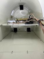
Looking at your shots, its clear that someone added a lot of stuff to that shelf after the airframe was constructed, but didn’t relish working back there enough to actually hide the wiring (and keep it from getting snagged anytime you put things back there). This could be a “while you’re in there…” time to re-route some of that stuff and make the baggage area cleaner. The road to hell is paved with good intentions….
View attachment 102247View attachment 102248View attachment 102249View attachment 102250
This can be a relatively hazardous test, plus determining the height flown requires the use of another person. If you do this, be careful.Any way you can safely record or log your indicated altitude close to the runway near stall speeds? That should confirm if/that you have a static port problem near stall speeds.
You’re correct - my port is in your location “A”, behind the bulkhead, and above the floor level. The plumbing is out of sight behind the bulkhead.Thanks, Paul! That’s exactly the kind of information I’m looking for. Other known good (or known suboptimal) location data is welcome!
If that location on your Rocket is below the floor, you must have built your floor on the upper longeron (mine is on the middle one).
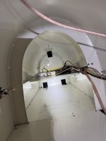
The attached photo shows my arrangement from the outside, along with my potential static port locations. I tend to favor “A” for having it protected behind the aft bulkhead, but above the floor level, where it’ll be (relatively) easier to reach for installation and troubleshooting. Vince’s is in location “B”. Location “C” would be the easiest to install, but adds more stuff to snag in the aft cargo area.
Yes, the area above the shelf is a bit cluttered. The original builder just had an ADAHRS and associated wiring and pitot/static tubing on a narrow shelf back there. The subsequent owner had an avionics shop install ADS-B in and out when ADS-B became obligatory. They added the “front” shelf and a bunch of associated wiring and coax cables. It appears that owner just wanted it to work, and didn’t much care what it looked like behind the back seat. I’ll have to give some thought to how all that stuff could be rerouted - or maybe just protected with some conduit?
Why not go to the source? John Harmon @ Bakersfield South?Since I’m now pretty committed to adding static ports to the aft fuselage, can I get some input on EXACTLY where others have had good results in F1 Rockets?
A photo that Vince Frazier shared of his original Rocket would indicate that they were just aft of the rear bulkhead (with “F1 Rocket” on it) and below the level of the cargo area floor in the attached photos.
But a photo from a link earlier in this thread shows the ports installed just forward of that aft bulkhead and just above the level of the floor in my airplane.
The second option would certainly be easier to install, but would leave the static ports/lines exposed in the aft portion of the cargo area, and therefore more vulnerable to damage when loading long items.
So both locations have advantages and drawbacks. From reading the Kitplanes article linked earlier in the thread, it appears that a few inches of horizontal and/or vertical movement can make a significant difference in whether the ports are in a positive, neutral, or negative pressure region of the airflow along the fuselage.
What’s most important to me is the optimum location for accurate readings based on other’s experience.
I’d love to know where YOUR static ports are, relative to that aft bulkhead and the stringer that the cargo area floor is resting on.
Thanks!
We all need to chip in and get John a Starlink Mni and service at his house up in the mountains so we can keep him in contact!Why not go to the source? John Harmon @ Bakersfield South?

Paul I built it (original builder) and it was very clean. Mine was the #3 F1 Rocket and a lot of learning was happening. Blue Mountain stuff followed by Dynon first gen Skyview. I was one of Mark Fredericks best salesmen in the day. I gave a bunch of rides and a lot of F1's resulted. The follow on owner had one of these pathetic avionics shops schlepp junk and wires back there. It makes me sad to see. I am confident Pete will clean it up and yes I take full ownership of the forward static port. Please note that on my current Glasair 3RG I put the static ports in the rear plus it's all Garmin. That's part of the education in "experimental."Here are a few shots for you that I quickly did in my hangar/shop just now - The (not flying) F1, RV-8, RV-6, and RV-3. I added vertical red lines on a couple of them to show the bulkheads. All three of the flying airplanes have very accurate ASI readings acros the speed range, but you’ll see significant variation in position relative to the longerons and tail. But… they are all sort of in the middle of the large flat side of the fuselage. The RV-8 is located exactly per plans, the RV-3 plans gave no location, and the RV-6 is located wherever Mike Seager (the builder of this serial number 4….) thought was a good location - and it turned out excellent. I located the F1’s based on looking at all of the various plans locations I had available.
I wanted the plumbing hidden on the F1, so I put it BELOW the floor of the baggage compartment (which sits on the longerons) and behind the aft-most bulkhead. I am fairly confident, based on experience with the other airframes, that it will turn out fine.
Looking at your shots, its clear that someone added a lot of stuff to that shelf after the airframe was constructed, but didn’t relish working back there enough to actually hide the wiring (and keep it from getting snagged anytime you put things back there). This could be a “while you’re in there…” time to re-route some of that stuff and make the baggage area cleaner. The road to hell is paved with good intentions….
View attachment 102247View attachment 102248View attachment 102249View attachment 102250
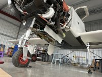
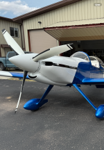
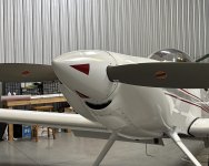
I have no idea what that is, but I want it. Is that a turbo -10 retract?Here’s a teaser of the latest ankle biter with rear static portsThis is for serious guys only….
Glasair 3RG, one of Jeff Lavelle’s old engines zero timed. You can’t have itI have no idea what that is, but I want it. Is that a turbo -10 retract?
That is a seriously cool plane!Glasair 3RG, one of Jeff Lavelle’s old engines zero timed. You can’t have it
It IS!......for point to point traveling. For flying enjoyment, it doesn't compare to an RV.That is a seriously cool plane!
Was suggested to me but never dared looking inside that close to the ground. So I was thinking about using EFIS logs, finding some way to identify lift-off and touchdown points in the logs.This can be a relatively hazardous test, plus determining the height flown requires the use of another person. If you do this, be careful.
Dave
It’s even better. Remember I’ve built a rocket & know. Glasair lost the kit war because composite is a serious pain to build. Don’t get me started about CF! Have you seen a riveted F1 car? I’m just too stubborn to quit building. Fly next few weeks.It IS!......for point to point traveling. For flying enjoyment, it doesn't compare to an RV.

Was suggested to me but never dared looking inside that close to the ground. So I was thinking about using EFIS logs, finding some way to identify lift-off and touchdown points in the logs.
I’d be happy to…. I’ll start a new thread when I have some good numbers. I hope others will share their numbers so we can compare, and have a good baseline for the next guy who (like I was) is starting with no published numbers.Outstanding!!!
If you wouldn’t mind, it would be great if you posted up your performance numbers as you validate your planes envelope. The Rockets are few, the configurations are many, and the curiosity is great!
Dang it….I LOVE a good engineering win!!!Posting to close the loop and conclude the story…
Last week I installed static ports in the aft fuselage. I got the clones of the Van’s pop rivet design from Showplanes. Then disconnected the static ports in the forward fuselage and sealed the lines up there.
Flight testing now gives me a Vso of 55 KIAS, and a Vs1 of 59 KIAS. Power-on stalls happen consistently at 45 KIAS.
Ground speed on short final (from Skyview) correlates well with TAS adjusted for reported headwind.
Then did a speed test box at 160 KIAS. I had very consistent winds displayed on all 4 legs - varied by 6° and 1.2 kts, and the TAS had a variation of 0.8 kts and a std dev of 0.5 across all 4 legs. I’m considering it a win.
The forward fuselage location was clearly inaccurate at higher AOAs (below 90 KIAS).
Thanks to all for the input - I’m considering this problem solved, and am moving on to performance testing.
I did a climb and glide sawtooth flight earlier this week and am in the midst of data reduction now.

It’d be pretty boring… with the static ports in the forward fuselage, all power-off stalls (w/ flaps or clean) and minimum speed slow flight all showed 70-72 KIAS. Above 100 KIAS, speeds seemed to be pretty valid.A table with side-by -side before/after numbers would be interesting; to me at least.
New static ports that are closer to the Van’s shape are on my very short list of things to do to my Rocket. Honestly, I’m just scared to touch the paint because it’s so darned perfect!Outstanding!!!
If you wouldn’t mind, it would be great if you posted up your performance numbers as you validate your planes envelope. The Rockets are few, the configurations are many, and the curiosity is great!
May I ask what altitude you’re doing those speed runs at? I don’t think I’ve seen above 22” MAP since I’ve been flying my Rocket (with a field elevation of 6900’). I’ve typically been flying between 8,000-10,000’ MSL. I just looked at my Skyview downloaded data from the performance testing- with full-power climbs at 2600 rpm, I peak out at 22”.New static ports that are closer to the Van’s shape are on my very short list of things to do to my Rocket. Honestly, I’m just scared to touch the paint because it’s so darned perfect!
I did speed runs again last week at 24-squared and came up with 201.5 KTAS. My Garmin screens were showing 186 KTAS. This is with absolutely beautiful, but absolutely flush static ports in the standard Van’s location forward of the horizontal stabilizer.
I’d be thrilled to achieve the accuracy Gyro has accomplished. Once I do, I plan to do some pretty thorough flight testing and will happily share my results.

It has it's own mission and RV's have a different mission. Both are great airplanes!It IS!......for point to point traveling. For flying enjoyment, it doesn't compare to an RV.
Sounds like we have the same/similar intakes (I believe there were two variations of the “smile”).Please describe your intake design.
I have the Harmon “P-51” smile with a cone-shaped K&N right in front of the servo.
I think this design is robbing a lot of power.
My last takeoff:
5100 msl
35 F
30.10
20 degrees fixed timing.
I saw 23.3” MAP at liftoff.
If I read the IO-540 D series chart correctly, 25.3 MAP or 241 HP should be available. I assume that is with 100% induction efficiency. If we assume a 1” reduction given normal induction inefficiency I’m still missing an inch of MAP or about 12 HP.
I don’t know how much I’m giving up with my timing set 5 degrees low or what I gain with my 9:1 pistons.
FWIW: the SDS MAP indicates .5 in higher than my G3X from which the nos. above are derived.