

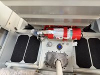
With John Stahr coming next week to put paint on the outside of the Rocket project, I have been busy making sure that everything truly fits together. While waiting for bits and spots of filler and primer to cure I decided it was time to finally assemble the interior completely all at the same time, so here it is! It will, of course, mostly come out for the AWC inspection, but at least now I know that all the nutplates work, fasteners line up, the paint survived the building process…. And the permanent floor panels are riveted down (sharp eyes will see a few clecos for things that will get removed to expose critical flight control junctions for inspection). And yes, some nuts have been left off because the control surfaces and flaps all come off for paint.
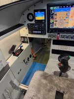
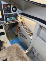
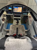
I get the most enjoyment personally when I build an airplane in making the cockpit my own - it may not fit anyone else, but things here are just where I want them - a nice office for myself, and a comfy place for a passenger. (AHRS, Magnetometer, G3X, G5 calibration are not yet complete - hence the weird mismatch in pitch between displays…)
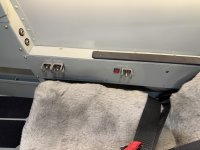
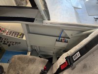
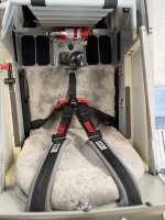
Note that I still have blue lo-tack vinyl on the storage compartments under my thighs - those serve as steps for entry and egress, and I figure I’ll leave them protected even through Phase 1 - then find something to cover them with for the future - perhaps clear skateboard tape. The entire painted interior was covered with that vinyl for the past two years and it did a great job of protecting the paint - and peeled right off when asked!
Haven’t decided what goes under my heels yet - but I have some ideas!

I get the most enjoyment personally when I build an airplane in making the cockpit my own - it may not fit anyone else, but things here are just where I want them - a nice office for myself, and a comfy place for a passenger. (AHRS, Magnetometer, G3X, G5 calibration are not yet complete - hence the weird mismatch in pitch between displays…)
Note that I still have blue lo-tack vinyl on the storage compartments under my thighs - those serve as steps for entry and egress, and I figure I’ll leave them protected even through Phase 1 - then find something to cover them with for the future - perhaps clear skateboard tape. The entire painted interior was covered with that vinyl for the past two years and it did a great job of protecting the paint - and peeled right off when asked!
Haven’t decided what goes under my heels yet - but I have some ideas!


")

 )
)