Van's Air Force

The definitive Van's Aircraft support community! Buying, building or flying an RV? Join our exclusive family of mentors and enthusiasts!

Landing Gear & Mount Drilling Issue

mhabib2011

I'm New Here
Hi All,

My landing gear & mount holes are elongated, all 3 of them. All drilled with new tooling. First one drilled with a cobalt drill bit, second one with a cobalt reamer and the third one with a cobalt reamer with carbide bits.

I had a call with Vans, and it seems like the issue is my mount and landing gear came undersized. Based on the phone call, I should only need to drill the back hole in the mount, instead my kit came undersized, and by drilling manually the long holes (mount front hole, landing gear, than mount back hole), the holes end up elongated, no matter how good the drill bit is, as the hand is bound to shake throughout the drilling.

To fix this issue, I was given the suggestion to use an "X" or "Y" bolt. As I can not go beyond that in size, I only have one chance to fix this without needing to buy all new hardware. So, I would like to check on the plan before I proceed. Also I have some open:
- I intend to disassemble the landing gear from the mount and drill the landing gear using a V bolk and drill press first with a slightly undersized cobalt drill bit, then with a cobalt reamer.
- I still do not see how I could drill the front hole in the mount precisely. I considered removing it to drill it with a drill press, but it is so bulky. Hand drilling is obviously not a good idea to get a precision hole. Any suggestions on how to drill the front mount hole precisely?
-
Once I have the front mount hole and the landing gear drilled, I will assemble all in the aircraft and clamp everything, to drill the back hole of the mount, first with the slightly undersized colt drill bit, then with the cobalt reamer.
- Where can I buy "X" or "Y" bolts? I do not see relevant results in google with this naming. The suggested company "genuine aircraft hardware" is not responding to email.
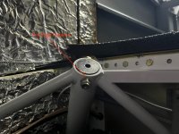
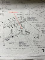
- I still have the open question of the small edge distance the mount came with from Vans. After drilling it became less: 0.17inch. After drilling to the next "X" or "Y" bolt size, it will become less. What is the minimum edge distance for the landing gear mount? Attached is a picture of what I am referring to.

Thanks,
 

Attachments

  • IMG_0107.jpg
    IMG_0107.jpg
    1.6 MB · Views: 119
  • IMG_0150.jpg
    IMG_0150.jpg
    2.2 MB · Views: 117
Last edited:
If hand drilling the gear legs then it helps to use a jig to align and guide the drill, that is how I drilled the main gear legs for my RV-6A. First drilled pilot hole 1/8" and then final hole 5/16" (the old kits do not have any holes drilled in main gear by factory). It is important to use cutting fluid and to drill slowly and not allow the parts to work harden.

It is strange that all 6 of your parts had under-sized holes as received. Normally only one of the holes in the sockets needs to be enlarged. What size were the holes in the parts when you received them?

The main gear legs should probably be clamped with the correct toe-in/out while drilling if the bolt holes are going to be enlarged further, to maintain correct alignment of the wheels.

This is a tricky operation for someone who doesn't have machining and fitting experience so it could be worth seeking help.

I'm not sure what is the acceptable edge distance but Vans support should be able to advise.
 
At least for the main gear, the holes are intentionally supposed to come slightly undersized from Vans, with the intention of using a .311” reamer to get the mount and gear holes final sized. That’s called out in the manual and plan drawings. What size did you open them up to?

If I’m following your process, you drilled the mounts and gear in separate steps. It’s very difficult to match parts up that way. Take a look at the drawing again - it mentions putting the gear leg into the mount, lining up the holes, and then drilling to .311”. If you have elongated holes now, I would be very hesitant to try to correct them without doing the mount and gear as one step/assembly. Whether it can be done by hand with the mount in the fuselage depends how bad the holes are at this point. You may very well have to remove the mount and use a drill press and jig. Do you have measurements or pictures of the holes? Did you elongate the holes in the gear, mount, or both?
 
Thanks for the responses. All my gear mount came undersized (I did not measure the hole, but it was not possible to pass a drill or a bolt with the socket through). I drilled the assembly together and that lead to elongated holes, where the long side is 0.03 inch to 0.04 inch bigger than AN5.

As I have been concerned about edge distance (from edge of the hole to edge of material), as I saw that it was very minimal:
  • measurement before drilling is 0.21inch (+/-0.02) with under sized hole
  • measurement after drilling: 0.19inch (+/-0.02) with elongated hole
I asked vans about the recommended edge distance and they responded with 2 diameter edge distance from the center of the hole; ie 0.625 inch. But the parts came very shy.

What is the edge distance you all have for these landing gear mount?
 
Last edited:
Thanks for the responses. All my gear mount came undersized (I did not measure the hole, but it was not possible to pass a drill or a bolt with the socket through). I drilled the assembly together and that lead to elongated holes, where the long side is 0.03 inch to 0.04 inch bigger than AN5.

As I have been concerned about edge distance, as I saw that it was very minimal:
  • measurement before drilling: 0.3125/2 + 0.22 = 0.37 inch (+/- 0.02inch)
  • measurement after drilling: 0.3125/2 + 0.17 = 0.32 inch (+/- 0.02inch)
I asked vans about the recommended edge distance and they responded with 2 diameter edge distance from the center of the hole; ie 0.625 inch. But the parts came with just 0.037inch, which is 0.25inch shy. The 0.03 inch undesirably removed by drilling is negligible when compared to the parts being shy 0.25 inch.

What is the edge distance you all have for these landing gear mount?
The edge distance for the bolts on my main gear leg mounts is 0.40 inch, measured from the centre of the bolt to the edge of the bracket.

20250405_095023.jpg


The drawing for the main gear leg indicates that the knob at the top is 0.75 wide and the bolt hole is centred on this. resulting in an edge distance of 0.375 inch.

20250405_094924.jpg

So it is interesting that Vans support has given advice (0.625 inch) that appears to contradict the drawings (0.375 inch). Perhaps it was generic advice that applies to e.g. rivet holes in aluminum sheet, rather than steel gear leg and bracket bolts.

As for the repair to your gear legs, an alternative to bigger bolts may be tapered pins, as some builders have posted about for repairing worn and elongated nose gear leg bolt holes. If you search on VAF there should be posts about what tapered reamer to use and what pins to purchase.
 
Standard edge distance does not apply to the landing gear. Drilling those "free hand" on an A model would be VERY difficult. The round landing gear was designed by Steve Wittman in the early 50's.
I drilled those holes freehand on several Wittman Tailwind's with tailwheel gear. For my current Tailwind I built a somewhat complicated drill jig that can accept multiple drill jig bushings.
Measure the oval portion of the holes with a dial caliper. That dimension will determine whether it is possible to use a standard oversize AN5 bolt.
If you don't have a dial caliper buy an inexpensive one. An alternative methos of measuring the hole is to create a no go gage from a scrap of aluminum. Cut and file to .321 which I believe is a standard oversize for AN5 bolts. If the gage goes in the oval portion
The gear socket repair is simple if you can find a welder with a TIG machine and superior welding skills. if the gear legs holes are too badly ovaled the gear legs may be scrap.
I will try to find my drill jig and also want to verify some dimensions on my Tailwind plans.
More to follow, probably not until Mon.
 
Hi All,

My landing gear & mount holes are elongated, all 3 of them. All drilled with new tooling. First one drilled with a cobalt drill bit, second one with a cobalt reamer and the third one with a cobalt reamer with carbide bits.

I had a call with Vans, and it seems like the issue is my mount and landing gear came undersized. Based on the phone call, I should only need to drill the back hole in the mount, instead my kit came undersized, and by drilling manually the long holes (mount front hole, landing gear, than mount back hole), the holes end up elongated, no matter how good the drill bit is, as the hand is bound to shake throughout the drilling.

To fix this issue, I was given the suggestion to use an "X" or "Y" bolt. As I can not go beyond that in size, I only have one chance to fix this without needing to buy all new hardware. So, I would like to check on the plan before I proceed. Also I have some open:
- I intend to disassemble the landing gear from the mount and drill the landing gear using a V bolk and drill press first with a slightly undersized cobalt drill bit, then with a cobalt reamer.
- I still do not see how I could drill the front hole in the mount precisely. I considered removing it to drill it with a drill press, but it is so bulky. Hand drilling is obviously not a good idea to get a precision hole. Any suggestions on how to drill the front mount hole precisely?
-
Once I have the front mount hole and the landing gear drilled, I will assemble all in the aircraft and clamp everything, to drill the back hole of the mount, first with the slightly undersized colt drill bit, then with the cobalt reamer.
- Where can I buy "X" or "Y" bolts? I do not see relevant results in google with this naming. The suggested company "genuine aircraft hardware" is not responding to email.
- I still have the open question of the small edge distance of one of the mounts that came with less distance, and after drilling it became less: 0.17inch. After drilling to the next "X" or "Y" bolt size, it will become less. What is the minimum edge distance for the landing gear mount? Attached is a picture of what I am referring to.

Thanks,
Genuine Aircraft Hardware has the bolts and piloted cobalt reamer you need. I suggest calling them. The X bolt for the nose gear is NAS6605-24X. I helped someone recently that purchased 3 #24 length and 3 #25 bolts and the cobalt piloted reamer for a little over $200, a couple weeks ago. Ive used the #24 length on 4 A model nose wheels, but he said the fit of the #25 was better. If the holes are already drilled initially, stop and wait for the proper reamer. I have done 4 by hand on flying airplanes without removing the gear. The reamer has an undersized pilot that keeps it aligned.
 
Whether or not a piloted reamer will work depends on how badly the holes are ovaled. AN bolts are slightly undersized next to the threads. Because of that I recommend using bolts that are one dash number over the recommended size. That insures that both ends of the bolts are properly sharing the load.
A slow turning drill and a good cutting oil are recommended.
 
For the next person the industry standard for drilling and reaming is the hole should be drilled 1/64 under the nominal size and then reamed. NOT the 1/32 undersize drill that Vans recommends. There are other options for next step. A series of reamers can be used starting with a reamer around .308 diameter. Then 309,310.311. By doing that the final reamer steps will be much more likely to follow the previous hole. Alternatively a expansion reamer can be used but they are somewhat fragile for this application.
Follow the same protocol for the oversize bolts.
High speed steel reamers are fine as long as the speed is slow and proper lubricant is used.
MSC supply is my source for reamers.If using oversize bolts get the bolts first and measure them to determine final reamer size.
 
Thanks all with all the advise. I greatly appreciate it.

I also been conversing with Vans aircraft on this, as I think this is safety critical and I want to make sure that the solution is good.

I am able to order NAS6605-29Y and NAS6605-27Y with a few sizes of piloted reamers from Genuine Aircraft Hardware. Thanks a lot for the recommendation.

My main worry that remains is the edge distance. One of my landing gear mount has only 0.017inch edge distance (distance from edge of the hole to the edge of material)! The others a are a little more. Vans aircraft responded twice with the instruction to proceed with the 0.017inch edge distance given that "There is no published minimum edge distance for 4130 Chrome molybdenum steel", "Due to the nature of the material (4130 Chrome Moly) the rules are not the same as for aluminum in its various grades. So long as the through bolts are sufficiently torqued the slightly lower edge distance will not be of any relevance in the functioning of the part and the ability of it to serve its designed purpose."

I am having a little hard time with the lack of "4130 Chrome molybdenum steel" edge distance data and the absence of a minimal requirement. Any advice you all have in the edge distance issue?
You can’t think in context of thin aluminum sheets. Edge distance rules are based upon material strength and sometimes thickness and sometimes load scenarios. Vans gives very general rules for edge distance because most all of the application of it is on very similar, thin aluminum parts. Once you step into a wider world of thick steel alloys, the rules are different and tend to be a bit more application / load specific. NOt an ME, so generalizing here. Maybe an ME will step in with data.f
 
Last edited:
Back
Top