

I am curious if anyone can help me understand part of A Dave Anders article in Nov 2023 Kitplanes p.47 titled "Build a Custom Plenum That Will Work."
The focus of my question is creating a pressure differential between upper cylinder plenum area and the lower area where the air flows to after it passes by the cylinder fins.
Dave says.....
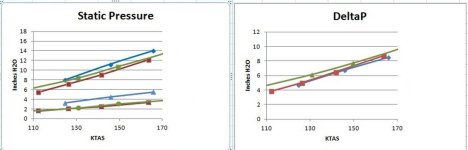
"If you don't have any help decreasing the (air) pressure under the cylinders from your exhaust your Delta P will be about 7 inches of H2O....."
"However with exhaust assistance lowering pressure in the lower plenum the delta p can be 11.5 inches of water."
Can you show me how folks building exhaust augmentation into their lower cowl to improve the pressure differential?
_________________________
My Original post is above this line.
Edit Oct 11th
My dad, a high school teacher,/coach from the 1950's - 80's once told me "Definition and nomenclature understanding is essential to learning. If the kiddies don't understand the words they cant learn the topic." I'm not too smart, but I'm curious. I took some terms used in posts below by the smart guys and included them here to help facilitate us slow guys to learn and keep up.
Mass airflow: Weight of Airflow per unit of time, like Pounds per Second. (we must understand that Air has mass....it weighs something and has inertia)
deltaP: Change in Pressure, or pressure ratio, or a pressure drop across a heat exchanger.
Coefficient: A multiplier. Like a better design has a better multiplier (coefficient) than a less efficient design.
Entrain: To draw along with or after.
Exhaust Augmenter: An outer tube (commonly a tube but also another shape or an area) that an exhaust pipe exits into. Air entrainment in the tube (area) by the moving exhaust air is a strong motive force that increases air flow through the augmenter tube.
Freestream: The air speed at the start.
Goal of a cooling System: Dan's key words "twin design goals are reducing the quantity of air and making it exit with velocity close to freestream.
Fineness ration: The ratio of the length of a body to its max width. Like an arrow has a large fineness ratio. So a smaller cowl inlet gives a larger fineness ratio.
The focus of my question is creating a pressure differential between upper cylinder plenum area and the lower area where the air flows to after it passes by the cylinder fins.
Dave says.....
"If you don't have any help decreasing the (air) pressure under the cylinders from your exhaust your Delta P will be about 7 inches of H2O....."
"However with exhaust assistance lowering pressure in the lower plenum the delta p can be 11.5 inches of water."
Can you show me how folks building exhaust augmentation into their lower cowl to improve the pressure differential?
_________________________
My Original post is above this line.
Edit Oct 11th
My dad, a high school teacher,/coach from the 1950's - 80's once told me "Definition and nomenclature understanding is essential to learning. If the kiddies don't understand the words they cant learn the topic." I'm not too smart, but I'm curious. I took some terms used in posts below by the smart guys and included them here to help facilitate us slow guys to learn and keep up.
Mass airflow: Weight of Airflow per unit of time, like Pounds per Second. (we must understand that Air has mass....it weighs something and has inertia)
deltaP: Change in Pressure, or pressure ratio, or a pressure drop across a heat exchanger.
Coefficient: A multiplier. Like a better design has a better multiplier (coefficient) than a less efficient design.
Entrain: To draw along with or after.
Exhaust Augmenter: An outer tube (commonly a tube but also another shape or an area) that an exhaust pipe exits into. Air entrainment in the tube (area) by the moving exhaust air is a strong motive force that increases air flow through the augmenter tube.
Freestream: The air speed at the start.
Goal of a cooling System: Dan's key words "twin design goals are reducing the quantity of air and making it exit with velocity close to freestream.
Fineness ration: The ratio of the length of a body to its max width. Like an arrow has a large fineness ratio. So a smaller cowl inlet gives a larger fineness ratio.
Last edited:
")

