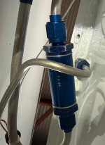
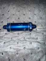
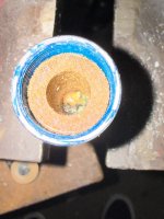
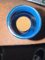
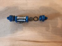
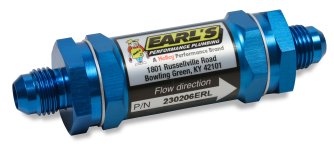
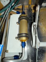
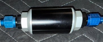
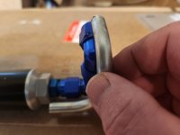
You won't clog the fuel flow sensor with typical granular debris, only chunks of silicone sealant, or fuel lube, or similar. Nor will a jammed rotor stop the flow. That said, the fuel flow sensor (assumed to be a red cube) introduces an additional unknown pressure drop prior to the electric pump....added to all the others contemplated. Note the 0.141" orifice.
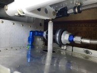
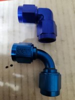
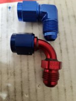
The cube belongs on the pressure side, downstream of the all the screens and pumps. Adding wing root filters, with additional 90's, to protect a cube installed in the wrong place is a classic example of "The road to hell is paved with good intentions".
View attachment 108634
Let's review. The issue is
not flow rate. It is vapor bubble formation. Lower pressure and/or higher temperature = more bubbles. Bubbles don't pump.
Pressure on the suction side of the pumps is below atmospheric, so vapor bubbles form at a lower temperature. Pressure on the downstream side of the pumps is higher than atmospheric, so higher temperatures can be tolerated.
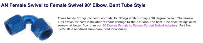
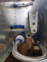
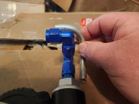
Sharp corners are a wildcard. Turning the flow around an edge tends to form a little region of low pressure. Given it's hard to quantify, good practice says design them out when possible, in particular on the suction side. It's not always possible.
A bit of caution may be in order. The RV-14 installations, being 390's not approved for mogas, see only a steady diet of 100LL, specifically formulated to maintain low vapor pressure. A mogas user with a different RV could get in trouble with the same collection of wing root 90's. Consider a load of high RVP winter blend mogas on a warm spring day, with the sun warming the tank.