auburnaviator
Well Known Member
This isn’t airplane related (except for the fact that it’s a relay on my shop A/C where I’m building my airplane) so if the thread isn’t appropriate please move/delete it. I went in to the shop this morning to start working on the plane and immediately knew something was wrong with the A/C. The fan was running but the compressor wasn’t so after some troubleshooting I narrowed it down to the compressor relay on the circuit board. If I jump the relay the compressor runs just fine.
So now I need to test the relay to see if it is bad or if something on the circuit board has gone bad. Looking at the back of the PCB it only appears that 1 of the four pins on the relay has a trace on it and the trace has good continuity with other pins that it runs to on the back of the board.
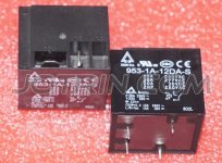
Just for reference the power wire ran to the COM terminal and the compressor feed line came off of the NO terminal and run to a solid state relay before continuing on to the compressor. The problem is I don’t know how to test the “bad” relay. Reference the attached relay picture. How do I test this with my multimeter?
So now I need to test the relay to see if it is bad or if something on the circuit board has gone bad. Looking at the back of the PCB it only appears that 1 of the four pins on the relay has a trace on it and the trace has good continuity with other pins that it runs to on the back of the board.
Just for reference the power wire ran to the COM terminal and the compressor feed line came off of the NO terminal and run to a solid state relay before continuing on to the compressor. The problem is I don’t know how to test the “bad” relay. Reference the attached relay picture. How do I test this with my multimeter?