sent this question to Vans, but given the current business situation figured may not receive a reply for a while....so now asking those that have done this before me...
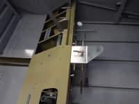
Going with the RV7 fuel value box set up, vs what’s called for in the RV6A 49 drawing (calls for a vertical throttle/prop/mixture assembly)…Im going with the horizontal bracket attached to the bottom of the panel.
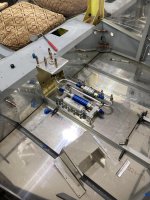
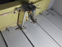
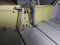
Ordered/received the RV7 materials for the fuel selector mounting (aka box).
Question is the 7 (36A) drawings don’t show how this attaches to the spar, so wondering how others have approached this. Obviously, pictures are also appreciated.
thanks for helping.
Going with the RV7 fuel value box set up, vs what’s called for in the RV6A 49 drawing (calls for a vertical throttle/prop/mixture assembly)…Im going with the horizontal bracket attached to the bottom of the panel.
Ordered/received the RV7 materials for the fuel selector mounting (aka box).
Question is the 7 (36A) drawings don’t show how this attaches to the spar, so wondering how others have approached this. Obviously, pictures are also appreciated.
thanks for helping.