Van's Air Force

The definitive Van's Aircraft support community! Buying, building or flying an RV? Join our exclusive family of mentors and enthusiasts!

How adequate is this radio stack support structure?

idubrov

Well Known Member
I'm designing a supporting structure for a radio stack on a slider RV7.

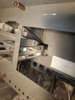
So the idea I have is to put two "ribs" spaced 6.330" so that Garmin racks can be installed between them. These ribs will be screwed to the subpanel and to the panel (via an aft and a forward angle).

IMG_9412.jpeg

A short autopilot rack at the top will be screwed just to the aft angle. Long equipment (audio panel, navigator and a second radio) will be screwed to these ribs as well.

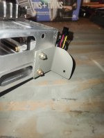
The ribs are made from a scrap LCP 0.032" fuel tank baffles (which is why they come with "predrilled" flanges). The forward angle at the subpanel is 0.062" 3/4" x 3/4" angle, and the aft angle at the panel will be 0.062" 1"x1" (the one on the photo is just a scrap piece, the real angle will be as tall as the whole stack).

Both angles will be attached to the subpanel / panel with #8 screws. I think, 4x #8 screws each? Is that enough?

Is that an adequate support for a radio stack?
 
Structure looks OK to me, BUT...suggest you check the lengths of your radios. On my RV-9A slider my nav/com (GTN650xi) protruded through the subpanel bulkhead. And all the wiring from the display units and radios also did, resulting in a big hole through the bulkhead. I ended up gusseting down from the bottom flange and adding a 1" x 1" aluminum tube to restore the subpanel strength. In addition, be careful of the clearance to the center rib between the firewall and the instrument panel. I purposely offset my radio stack to the right so they would miss the rib. Others have cut the rib and reinforced it but I didn't want to do that.
 
30-years ago when I built my RV-6 slider, I only used 3/4" X 3/4" X 1/8" angle vertically both sides on the panel and on the both sides of the hole I cut in the bulkhead between firewall and panel. The radio trays for my radios only need screws in the front and the back. The idea came from "certificated" aircraft that could have radios changed out in the future just by drilling new holes and captive nuts relocated on the angles.
 
Tensile strength of 2024-T3 Aluminum alloy is 50Kpsi.
Shear yield of a AN515-8R8 screw is 36Kpsi (60% of tensile yield) ===> 760lbs in shear for a #8 screw)
Figure in the size of the material (thickness) and weight (@6G) of structure to be supported in all axis, and you should be able to derive your answer.

(ed. You built a brick house, no wolf is going to blow that door in ;) )
 
I’ve been working with my avionics shop planning and doing the prep and rework for my -7 tip up IFR panel.

For my rework the location of the radio stack is nailed down to placing it adjacent to the existing structure. The depth of the radios dictated that I cut a window in the sub panel. I reinforced that window opening with aluminium angle all the way around. The shop had me use the lower edge of that opening to physically support the back side of the radio stack.

The window in the sub panel also has the depth to accommodate future upgrades.

In order to make room for the G3X I made cuts to bend the fore/aft support from the sub panel to the panel in front of the pilot and made an additional support to connect the bent support to the panel.

Before you get too far down the rabbit hole. Get a panel design made and triple check that everything can work. My shop cut my panel 3 times in clear plastic to verify everything before doing it with the real Sheetmetal.

Another thing. I had paid an outfit start to making a panel design for my -7. Their design didn’t accommodate any of the existing structure of my aircraft…..

When I removed my old panel I had to disconnect every f*^*ing wire to get the panel out. Working with my avionics shop. We made all the switches and circuit breakers on a separate piece of metal connected by angle aluminium bar just below the main panel and slightly recessed. This Lower bar also has the throttle/engine controls.

In the future, any of that work is separated into two sections. Upper panel, and the engine controls, switches, and circuit breakers below. Way easier to work on with extra holes pre-cut for future switches and upgrades.
 
Structure looks OK to me, BUT...suggest you check the lengths of your radios. On my RV-9A slider my nav/com (GTN650xi) protruded through the subpanel bulkhead. And all the wiring from the display units and radios also did, resulting in a big hole through the bulkhead. I ended up gusseting down from the bottom flange and adding a 1" x 1" aluminum tube to restore the subpanel strength.

Yes, I'll have to cut a hole in the subpanel for the GTR200 radio and for the GTN650xi navigator.

In addition, be careful of the clearance to the center rib between the firewall and the instrument panel. I purposely offset my radio stack to the right so they would miss the rib. Others have cut the rib and reinforced it but I didn't want to do that.

I'm using Aerosport panel, and it offsets the radio stack by ~1-3/16" to the front. With the thickness of the panel (1/16"), it gives me 1.250" distance from the face of the radio stack insert to this central rib. And Autopilot GMC507 is 1.150". I think, I will be able to place it in front of the rib, at the very top of that opening in the photo.

I haven't trimmed my carbon fiber panel part yet to verify, so this is a bit of a theory (but supported by my measurements / STEP files from Garmin / GMC507 rack I already have).

Looking at GMC507 STEP file, I see that it has connector to one side so it shouldn't interfere with the rib as well. GMA 245 audio panel placed just below the GMC507 should clear the rib as well. And then GTN650Xi and GTR200 would require a hole.

Everything I want seems to fit, but just barely. I 3D printed STEP files from Garmin to play with real sized mocks.
 
Tensile strength of 2024-T3 Aluminum alloy is 50Kpsi.
Shear yield of a AN515-8R8 screw is 36Kpsi (60% of tensile yield) ===> 760lbs in shear for a #8 screw)
Figure in the size of the material (thickness) and weight (@6G) of structure to be supported in all axis, and you should be able to derive your answer.

(ed. You built a brick house, no wolf is going to blow that door in ;) )
I am not quite sure what you are trying to accomplish with what you are showing in the pic. You really don’t need to span a plate or angle from panel to subpanel. You need an angle to be able to attach the instrument tray on the panel and an angle on the subpanel to attach the instruments to. The instrument frame itself becomes the structural tie from panel to subpanel.

(ed. You built a brick house, no wolf is going to blow that door in ;) )
This ^^
 
I am not quite sure what you are trying to accomplish with what you are showing in the pic. You really don’t need to span a plate or angle from panel to subpanel. You need an angle to be able to attach the instrument tray on the panel and an angle on the subpanel. The instrument frame itself becomes the structural tie from panel to subpanel.
What is an "instrument frame"? Audio panel rack, for example, is not long enough to reach the subpanel. All racks seems to have their "rear" (forward, relative to the airplane) screws placed at different "depth". Which is why I thought of using these ribs and adding nutplates where needed on them.
 
What is an "instrument frame"? Audio panel rack, for example, is not long enough to reach the subpanel. All racks seems to have their "rear" (forward, relative to the airplane) screws placed at different "depth". Which is why I thought of using these ribs and adding nutplates where needed on them.
If you have at least one of the radios that has to penetrate the subpanel, that rack will serve as the support for ALL the other radio racks. Even if it does not penetrate the subpanel and it is close to it, you can mount an angle to the subpanel that you can screw the back of the tray to and secure it. Then you can simply use a vertical piece of angle or even possibly a strip of aluminum with nutplates attached that would align with screw holes on the shorter radios. That would then also have the one tray penetrating the subpanel screwed to it. That would tie ALL of those radios to that instrument tray spanning the distance. This provides structural strength and stability without adding weight.
 
If you have at least one of the radios that has to penetrate the subpanel, that rack will serve as the support for ALL the other radio racks. Even if it does not penetrate the subpanel and it is close to it, you can mount an angle to the subpanel that you can screw the back of the tray to and secure it. Then you can simply use a vertical piece of angle or even possibly a strip of aluminum with nutplates attached that would align with screw holes on the shorter radios. That would then also have the one tray penetrating the subpanel screwed to it. That would tie ALL of those radios to that instrument tray spanning the distance. This provides structural strength and stability without adding weight.
A picture is worth a thousand words

IMG_7756.jpeg
 
Not an RV-7, but did this work on my new RV-10 project.

The hardest part was deciding where the hole in the next forward bulkhead needed go to fit the big, clunky GTN-650. For the RV-10 I also cut the center rib (and added a piece of .125” aluminum plate to reenforce the rib cut) to allow the GTN650 to be mounted as high as possible. The hole is reinforced with scrap J channel.

Note the rear brackets on the GTN tray. #8 screws attach the tray to the next forward bulkhead via nut plates. So a solid mount forward and aft.

The radio stack comes out with the panel.

Carl
 

Attachments

  • 20250724_144728.jpeg
    20250724_144728.jpeg
    3.8 MB · Views: 50
  • 20250724_145143.jpeg
    20250724_145143.jpeg
    2 MB · Views: 46
Back
Top