I started another thread recently looking for recommendations for shops that would build custom harnesses for me to accommodate my AeroLED VXi lights. Basically everybody just said do it myself so I'm going to see how far I can get trying it myself - with your help! Here's where I'm at- I'm building an RV-14 and I purchased AeroLED VXi wing tip lights without knowing they are not compatible with the factory harnesses. Yeah, I'm a new builder.
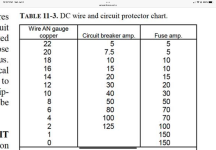
I need 12 wires in total as shown below. I estimated the size of the wires by using a 25' wire run and referencing the load on each wire against the chart in the FAA AC43.13-1B document. The wires will probably be a little shorter than 25' but I want to error on the side of safety. AeroLED recommends using three strands of four conductor shielded wire.
My questions-
1- How should I group the wires within the 3 strands of each conductor? Power wires together (12awg), then grounds (14awg) then the rest (20awg)?
2- Where can I source shielded 4 conductor 12awg and 14awg wire? I came up empty. Links would be greatly appreciated.
3- Any idea why AeroLED says there are 27 amps of ground (per the comment on their wiring diagram below)? I only came up with 19 amps (see below).


AeroLED VXi wiring diagram

FAA AC43.13-1B....

I need 12 wires in total as shown below. I estimated the size of the wires by using a 25' wire run and referencing the load on each wire against the chart in the FAA AC43.13-1B document. The wires will probably be a little shorter than 25' but I want to error on the side of safety. AeroLED recommends using three strands of four conductor shielded wire.
My questions-
1- How should I group the wires within the 3 strands of each conductor? Power wires together (12awg), then grounds (14awg) then the rest (20awg)?
2- Where can I source shielded 4 conductor 12awg and 14awg wire? I came up empty. Links would be greatly appreciated.
3- Any idea why AeroLED says there are 27 amps of ground (per the comment on their wiring diagram below)? I only came up with 19 amps (see below).
AeroLED VXi wiring diagram
FAA AC43.13-1B....