Van's Air Force

The definitive Van's Aircraft support community! Buying, building or flying an RV? Join our exclusive family of mentors and enthusiasts!

Harness layout (how to start)

toolmanmike

Well Known Member
Friend
I see all these pics of beautiful wire harnesses payed out on a board with lables and clamps just waiting to be installed. I have a board- it is blank. Where do I start? I have loads of wire and a good schematic from Stein. All my equipment is mounted in the plane. I even have Most of the distances for the wire runs worked out. Still don’t know where to start.

1 thought is to start with power and make those runs first.
1 thought is to start at the PFD and go from there, 1 wire at a time
1 thought is to start with the CAN buss layout and work from that.

Lots of thoughts. No action. I just sit here and stair at the blank board.

Those who have done this- give me something. I feel like I have a tank of gas and no where to go.

Toolman
 
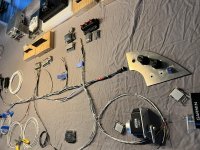
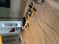
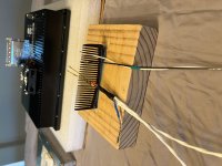
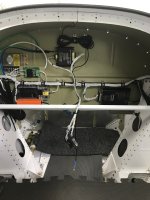
Don't know if this is the "right" way, but there's how I approached it (harnessed, installed, tested, but not yet flying). I took the AEA class and have some industrial wiring experience, but nothing beyond that.

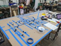
Start by figuring out the general shape of your harness. I decided:
1) I'd have one central trunk that ran along the bottom of the subpanel
2) Branches would loop up from that to each of the components on the panel. That way, the connectors would dangle down below the panel if I ever needed to work on them in the plane.
3) I'd have small bundles (basically just headset and USB power) that went out the left and right side of my main trunk.
4) I'd have two big bundles that went down right from the center of the trunk to everything aft -- one for stuff that would split and go to the wings, one would go back to the flaps and everything aft of that.

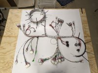
With that general design in mind, I taped a 1" PVC pipe to represent my main trunk on to the subpanel, and then marked off 1" increments from left to right on that. I used a flexible tape measure to then measure how long the branch to each component would be, and recorded the length and what increment on the main trunk that was. Then I could lay that out on my board in tape. I actually did this all from a mockup of the panel (I hadn't even gotten my fuselage kit yet), so was a little nervous about wire lengths, but I had one wire in the entire plane that was too short and needed to be spliced (and that was because I reversed the locations of the trim servo and the magnetometer in my head).

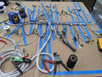
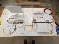
I started by doing the CAN bus for all components, and then just picked one connector and started running every wire out from there -- powers, grounds, signals, etc. Repeat for each connector and you have the whole harness run, then it's just a matter of terminating the connectors, lacing and installing.

Doing it one connector at a time made it easy to make sure I wasn't missing anything. I did have a wirelist (in addition to per-device diagrams), which made it easy to not run duplicate wires -- every wire appeared on my wirelist exactly once, so by the last connector there were no new wires to run; the earlier connectors had gotten them all.

Took about 20 hours over a week to run and terminate all the connectors. Only issues I had were from my own misreading of Garmin's instructions about which protocols were available on which RS-232 ports.
 

Attachments

  • PXL_20220816_145947671 (1).jpg
    PXL_20220816_145947671 (1).jpg
    511.3 KB · Views: 360
  • PXL_20220823_161429204.jpg
    PXL_20220823_161429204.jpg
    592.2 KB · Views: 316
One wire

Throw a dart at the schematic and do that wire first. Then do an adjacent wire. And so on.

Dave

I'm a one cable at a time guy too!
All the gadgets were mounted first with consideration to future maintenance. Gadgets I need to access are on two hunged panels. Hinged both fore and aft so they can be removed in seconds.
Wiring was started FWF. Every gadget and gizmo wired. Estimations were done with a scrap piece of Cat-5 cable. Also serves as a snake. Tie on and pull. Lots of wires come in or go forward. The EMS was the big Kahuna. I actually terminated the 37-pin to a D-sub firewall forward. Its much eaiser to terminate all the sensors to the male D-sub. Maintenance is just two screws to separate the D-sub. It's also lashed together.
Now on to end of the tail forward. Lights, pitch trim, ADAHRS, pitch servo. Then flaps, sticks, aileron trim, wing wires.
I have the Advanced panel-less panel so all the gizmo cables are done. Plug and play.
 
Layout

I too used a tube to attach the main Trunkline ,in my application i used a Carbonfiber arrow shaft . I also used Combs to keep the wires separate and in a neat order . I started with fabricating the CanBus first then used that as my template to continue with the rest of the harness
 

Attachments

  • F2473F0E-9E02-46D1-9E58-DD191168DAF0.jpg
    F2473F0E-9E02-46D1-9E58-DD191168DAF0.jpg
    496.9 KB · Views: 286
  • BF3A5C9A-1D76-4BC1-979A-53F15BCA5265.jpg
    BF3A5C9A-1D76-4BC1-979A-53F15BCA5265.jpg
    396 KB · Views: 230
  • 0BD0F7F3-6B8E-44F9-9339-E32FAA728B20.jpg
    0BD0F7F3-6B8E-44F9-9339-E32FAA728B20.jpg
    476.2 KB · Views: 265
I too used a tube to attach the main Trunkline ,in my application i used a Carbonfiber arrow shaft . I also used Combs to keep the wires separate and in a neat order . I started with fabricating the CanBus first then used that as my template to continue with the rest of the harness

Loved the combs! Great idea.
 
SNIP…
Only issues I had were from my own misreading of Garmin's instructions about which protocols were available on which RS-232 ports.

Yep - this will bite you (as it already has for many). Assigning serial ports should be one of the first decisions.

Side note. Wire harness are great for production line work. For me however our one off planes lead me to think the effort is not worth the gain. I document the wire runs and connections in a work document. This provides the much needed reference data for maintenance and future modifications. One of my pet peeves is when a pilot asks me to help fix a problem and I look at the rats nest of wires in the plane and cringe. When I ask for wiring documentation (or even a simple block diagram) I get the expected answer. At that point my response is “looks like you have opportunity to redo your panel - from scratch”.

Build everything assuming you (or the new owner) will make changes, upgrades or need to fix something - because it will happen. If you built the panel so that it cannot be removed as an assembly your are already on the bad side of the curve. For those who farm out their panels make sure you discuss this with the shop doing the work.

Carl
 
I went for it.

This is how my work does it, but the customer usually gives us a 3 D model of the aircraft with the wire runs routed in 3D CAD.
I didn't feel like building a 3D model of my plane to establish a harness design.
So i started with the center radio stack, with just the trays attached to the panel, and then started routing wires from there.
then I added the forward ribs and bulkheads and continued wiring. All off the plane. So once the wiring was done, I installed the forward section into the fuselage, with it pre wired.
 
Hi!

Our approach was to build a mock up of the panel and sub panel, and use that to determine run length. Then we ran the power and ground wires to establish those lengths to the connectors. Then moved it to a board and matched those lengths for all the other runs.
 

Attachments

  • PXL_20220421_212644539.MP.jpg
    PXL_20220421_212644539.MP.jpg
    154.3 KB · Views: 233
  • PXL_20211127_222509816.MP.jpg
    PXL_20211127_222509816.MP.jpg
    174.5 KB · Views: 216
  • PXL_20211125_015219762.MP.jpg
    PXL_20211125_015219762.MP.jpg
    146.9 KB · Views: 180
Great help one and all! I have made the jump and started laying wires. Big help to me was “visualizing “ the harness layout as it will sit behind the sub panel. I started on a long wire run and just ticked them off from there.
Some gotchas- If your run goes through a bulkhead like a sub panel to reach the back of a deep radio stack- make sure you lable that on your board layout so you don’t start a “branch” that will end up on the wrong side of the bulkhead.

I think it was Paul on another post who said it is like eating an elephant. You just take 1 bite at a time.

Here is my layout so far. No CAN BUS yet and no power and grounds. IMG_4686.jpg
 
That's looking great. The two best tools you have on the table are the SteinAir sheath stripping block with razorblade. And the beer. 🙂
 
Would a DIN wire raceway be something that would work for a panel, or would the wires not be secured enough?
 
There are so many ways to skin that cat. I've been doing a few "new" installs for a flight school. It involves removing the old radio tray and harness, then routing the new wiring along existing bundles and terminating them where needed. This means any slop gets worked back into the bundle. I find its next to impossible to make the perfect cut, so Id rather do it that way then end up with a wire thats just a hair too short.

Doing the whole new install on my RV-8 build, I first figured out where every component was going to be mounted, mounting some of them temporarily with double sided tape. Needless to say the mounting locations changed a few times before I was happy with it.

The instrument panel was cut and powdercoated by Pacific Coast Avionics, so I mounted those components too.

Next, wired the aft sub panels, bringing those wire bundles forward. And then I decided what was going to be the most complex part of the avionics shelf wiring. Turns out its the radio stack, consisting of the GNS430, Audio Panel and Dynon Com radio. So that bundle is where I start. I lay each wire in by hand, bundling as I go. Some gets tie-wrapped, some just a temporary zip-tie or velcro.

I don't use the wire bench for one-off builds. Because I don't know exactly how the wire bundle will bend till I build it. Laying in each wire by hand, and tying as I go insures the bundle is not stressed in any of the bends.

When I worked at the repair depot, the wire benches were used to build up bundles when the exact dimensions and every bend was already exactly known.
 
Last edited:
Would a DIN wire raceway be something that would work for a panel, or would the wires not be secured enough?

You don't want wiring to be flopping around, for various reasons. Raceway would be fine if you were instrumenting a cabin class or larger aircraft where you were making frequent wiring changes. For small aircraft, string tie or ty-wrap (:() instead.
 
Question (sorry semi hijack) were do you route the wires through:
Firewall (one side, two sides, middle)
To Each Wing (behind main spar)
To Back (belly antenna, magnetometer, ELT)

Is there a drawing. Don't think Van's Aircraft shows that.
 
Sorry for the vague answer but like most things on your plane the answer depends on you and you equipment. Many here want the panel completely removable which means adding big d-sub connectors behind the panel and at the “head” of the wiring harness. Many chose to just run the harness without. Either way, you will need some significant runs if you have an IFR plane. I chose to run my harness from the sub panel through the tunnel where the fuel run is and then split it out before the main spar. 1/2 went left-1/2 went right and another 1/2 (I know!) went directly aft through the middle of the spar.
All my autopilot stuff is in 1 bundle (left) and runs under the baggage floor via pex tubeing to the autopilot servo. All my transponder, elt,and antenna wires go right and under the baggage through a separate pex pipe to my remote mounted transponder and elt. My heated seats, flap control, smoke control and misc. stuff go straight back.
So, you may need to use every available hole in the spar for wiring.

Under the panel- I cut 2 main pass through throughs in the sub panel behind the panel for wires to go and then routed those to 1 of my 3 branches.

This took a long time to map out but isn’t rocket science. Just work 1 wire at a time and send them the most efficient route you can. Biggest part is laying out where all the hardware will go. Then you can draw out your road map.

Hope it helps. This was one of the most frustrating and rewarding parts of the whole build.

Toolman
 
Build everything assuming you (or the new owner) will make changes, upgrades or need to fix something - because it will happen. If you built the panel so that it cannot be removed as an assembly your are already on the bad side of the curve. For those who farm out their panels make sure you discuss this with the shop doing the work.

Carl
I disagree with the above, in today's big screen world access behind the panel is easy with the large screens removed. Service loops on things in the radio stack so that connectors can be accessed and serviced also are important for future maintenance. IMO adding a slew of connectors to make the entire panel removeable just adds a ton of complexity and doubles the failure points. It's one thing to have connectors for lights and stuff but connectors on small signal wires on things like 232/429/Ethernet/CAN/audio should be avoided. Long term reliability will suffer with the more connectors you have.
I don't do "removable' panels for this reason and if a customer requests it, I will suggest he go somewhere else.

My installs are custom made for each aircraft and no two are exactly the same, so I use the panel we designed mounted to a table with a mockup subpanel with all the LRU's mounted as they will be in the aircraft. Radio stack is wired first then it just grows from there. For items not on the subpanel, pigtails are left long and after installing in the aircraft they are cut to proper length and connectors installed. All the switches and breakers are in the panel and their wiring is completed mostly on the bench. The entire harness is then removed from the bench and transferred to the aircraft.
 
Last edited:
I agree with Walt. As a retired industrial electrician, it has been my experience that the vast majority of electrical problems are due to bad connections. The less electrical connections there are, the less future problems there will be. I do not recommend terminal strips. A loose or corroded connection can cause intermittent problems which can be very difficult to troubleshoot.
 
The standard mil spec gold plated connector is rated for thousands of mate/demate cycles and has impressive electrical andenvironmental specifications. I have to ask what is more likely to cause a problem, a connector failure or damage from the tech to wiring trying to work behind the panel of a typical RV?

I only know about the RV8 and probably have the record for the simplest panel but being able to remove the panel is game changing.
 

Attachments

  • IMG_3698.jpeg
    IMG_3698.jpeg
    1.5 MB · Views: 61
  • IMG_0187.jpeg
    IMG_0187.jpeg
    2.4 MB · Views: 52
Last edited:
I’m guessing Walt and Joe are looking at the concept of a removable panel through the lens of “this is what we have always done”, as in what would need to be modified to make one of their panels removable. Wire harnesses assembled on the bench are just fine, but plan ahead.

I’m now building another full IFR, dual screen panel for the new RV-10 project. This includes the grossly over priced and clunky GTN-650XI. As with the other panel builds I divide what stays in the plane and what comes out with the panel. So:
- All the power distribution stuff, master and vital buss switches and breakers not associated with the radio stack stay in the plane. On the RV-10 these are all mounted on the stock Van’s lower panel apron and are fully accessible with panel out. On the RV-8 this stuff is mounted on the wings each side of the center panel or the normal right side lower panel.
- Remote modules include Comm #2, XPDR, EMS, ARINC module and ADS-b receiver. All but the ADS-b receiver are mounted on the bulkhead behind the panel ARINC module - so easy access once the panel is out. The ADS-b receiver is mounted aft near its associated antenna.
- The “impossible to work in the plane” radio stack tray connections come out with the panel.
- My “slew of connectors” to make this happen are one 25 pin, one 15 pin, the D connector that goes to the behind the panel ARINC module, and one power connection.

Side note - over 20 years I have never had a D connection fail.

My advice is to carefully select components and layouts that avoid making future work/maintenance/modifications so hard. While having the big EFIS holes are nice, my experience is they provide just enough access to tease you, not do what you need. Don’t break the rule of “never on your back with your head under the panel”.

Carl
 
Back
Top