Hello!
I'm (still) waiting on backordered parts, so I don't have the ability to actually roll my canopy frame on the mounts. I'm finishing up the last bit of wiring - antennas!
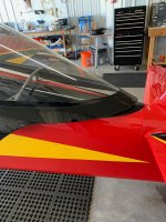
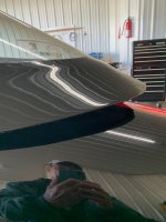
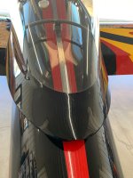
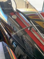
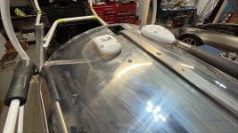
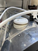
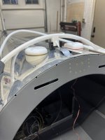
Would this location conflict with the frame at all as it moves? Or is it safe to place the antenna here?


I can't place it under the cowling due to plans on making a carbon fiber cowling down the road. As this needs to talk to satellites, it seems like this might be the next best place for it - but would it conflict at all with the movement of the canopy?
Thanks folks!
I'm (still) waiting on backordered parts, so I don't have the ability to actually roll my canopy frame on the mounts. I'm finishing up the last bit of wiring - antennas!
Would this location conflict with the frame at all as it moves? Or is it safe to place the antenna here?
I can't place it under the cowling due to plans on making a carbon fiber cowling down the road. As this needs to talk to satellites, it seems like this might be the next best place for it - but would it conflict at all with the movement of the canopy?
Thanks folks!


")