I had the connectors for my GSA 28 roll servo made at an avionics shop, got it back, and connected it to the servo. There is an extra two wire bundle and a ground wire from the connector. The shop said "connect the wires labeled Hi and Lo (from the bundled wire) to the CAN node. I can't find any useful (think non-avionics guy) assistance with this. Is the "CAN node" another connector that is tied into the other servo? The schematics from Garmin don't help.

Van's Air Force
You are using an out of date browser. It may not display this or other websites correctly.
You should upgrade or use an alternative browser.
You should upgrade or use an alternative browser.
GSA 28 wiring issue
- Thread starter rhrezo
- Start date

CAN Bus
I had the same question when installing my servo. The CAN bus is a commuication link between all the G3X components you have installed. The HI and LOW wires coming out of the servo get spliced into the HI and LOW CAN bus wires. Look at 2.3.1.3 in the install manual. The servo is an LRU. I cut the CAN bus wires and soldered the two ends with the wire coming out of the servo. Garmin support also sent me a diagram that helped.
I had the same question when installing my servo. The CAN bus is a commuication link between all the G3X components you have installed. The HI and LOW wires coming out of the servo get spliced into the HI and LOW CAN bus wires. Look at 2.3.1.3 in the install manual. The servo is an LRU. I cut the CAN bus wires and soldered the two ends with the wire coming out of the servo. Garmin support also sent me a diagram that helped.
Dbro172
Well Known Member
Study this Pic!
Im no Expert (pun intended) but I think your wires labeled Hi/lo are the node and what they meant to say was to connect them to the CAN Bus. In this photo, the wire that my fingers are pinching is the CAN bus. This is a mockup of my CAN bus from the GEA 24 to the GSU 25 to the GAD 29 with the GAD 29 at the end of the bus. you could also look at this as being the AP servos to the Left and right of my fingers, with the servo to the right of my fingers, at the end of the bus. (someone please correct me if im wrong here) By the way, this is just another example of the service from Stein air, this mockup was provided with my wiring harness for the GAD 29, showing exactly how to tap into the CAN bus.


Im no Expert (pun intended) but I think your wires labeled Hi/lo are the node and what they meant to say was to connect them to the CAN Bus. In this photo, the wire that my fingers are pinching is the CAN bus. This is a mockup of my CAN bus from the GEA 24 to the GSU 25 to the GAD 29 with the GAD 29 at the end of the bus. you could also look at this as being the AP servos to the Left and right of my fingers, with the servo to the right of my fingers, at the end of the bus. (someone please correct me if im wrong here) By the way, this is just another example of the service from Stein air, this mockup was provided with my wiring harness for the GAD 29, showing exactly how to tap into the CAN bus.
CAN Bus Wiring
Hello Richard,
The other responders have done a great job explaining CAN bus wiring. We also wanted to explain the 3 methods that can be used to connect a device (LRU) to the CAN bus backbone.
As a reminder, the CAN bus backbone is simply a twisted, shielded pair of 22 AWG wires that runs around the aircraft and connects all the G3X devices that communicate over the CAN bus.
As shown in the diagram below, there are 3 methods that customers use to connect devices to the CAN bus.
Method 1 is what Derek has shown above with two ends of the CAN bus going into the connector backshell at the device. Two short 22 AWG wires are spliced (typically soldered and heat shrinked) onto the CAN Hi and CAN Lo wires and two pins are crimped on. This is probably the most popular method of connecting to the CAN bus and works well.
Method 2 is a second method which has the advantage of not having the CAN bus splicing happening inside the backshell. With method 2, the splicing happens a few inches away in the CAN bus backbone, and a single twisted, shielded pair cable goes into the backshell where two pins are crimped on. Since your supplier provided a pre-wired servo connector, this may be the way you want to tie this into the CAN bus backbone, but remember that a CAN node (short run to CAN backbone) can only be a maximum of 1 meter in length.
Method 3 is something everyone will use exactly twice, since the devices connected to the extreme ends of the CAN bus are always connected in this very simple manner where the shielded, twisted pair CAN bus backbone enters the backshell and the shield is terminated there.
Let us know if we can answer any additional questions.
Thanks,
Steve

I had the connectors for my GSA 28 roll servo made at an avionics shop, got it back, and connected it to the servo. There is an extra two wire bundle and a ground wire from the connector. The shop said "connect the wires labeled Hi and Lo (from the bundled wire) to the CAN node. I can't find any useful (think non-avionics guy) assistance with this. Is the "CAN node" another connector that is tied into the other servo? The schematics from Garmin don't help.
Hello Richard,
The other responders have done a great job explaining CAN bus wiring. We also wanted to explain the 3 methods that can be used to connect a device (LRU) to the CAN bus backbone.
As a reminder, the CAN bus backbone is simply a twisted, shielded pair of 22 AWG wires that runs around the aircraft and connects all the G3X devices that communicate over the CAN bus.
As shown in the diagram below, there are 3 methods that customers use to connect devices to the CAN bus.
Method 1 is what Derek has shown above with two ends of the CAN bus going into the connector backshell at the device. Two short 22 AWG wires are spliced (typically soldered and heat shrinked) onto the CAN Hi and CAN Lo wires and two pins are crimped on. This is probably the most popular method of connecting to the CAN bus and works well.
Method 2 is a second method which has the advantage of not having the CAN bus splicing happening inside the backshell. With method 2, the splicing happens a few inches away in the CAN bus backbone, and a single twisted, shielded pair cable goes into the backshell where two pins are crimped on. Since your supplier provided a pre-wired servo connector, this may be the way you want to tie this into the CAN bus backbone, but remember that a CAN node (short run to CAN backbone) can only be a maximum of 1 meter in length.
Method 3 is something everyone will use exactly twice, since the devices connected to the extreme ends of the CAN bus are always connected in this very simple manner where the shielded, twisted pair CAN bus backbone enters the backshell and the shield is terminated there.
Let us know if we can answer any additional questions.
Thanks,
Steve
Last edited:


I think I've got this- the blue and white wire coming out of connector to servo are connected with a bridge wire to the other servo in the fuselage. Does it matter which servo I install a CAN Bus termination between pins 3 and 4?
The terminator must be installed at the END of the bus.
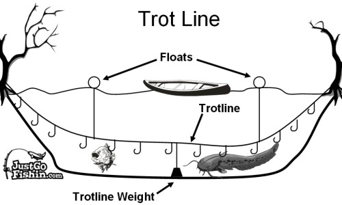
In my plane the CAN bus wire goes from the GSU 25 below the instrument panel, down the side of the fuselage to the front seat where it is spliced into a 2' wire connected to the roll servo, then continues on to the pitch servo in the back. The end of the CAN bus is where this wire terminates at the pitch servo. Your CAN bus is like a trot line where the individual units connected to the bus are like hooks connected to the main line by short individual lines. The first unit you wire up is like the tree in the image, and you connect a terminating resistor there. You then might go to your PFD, then your MFD, then your GSU 25, then a GSA 28, then end at another "tree" with the last GSA 28 and put a terminating resistor there as well.
Last edited:
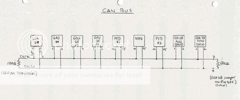
I think you need a schematic or sketch of your CAN bus. If you haven't done the wiring yourself, go back to the avionics shop that did and ask them to provide a schematic. Then you will be able to see where in the bus the pitch servo falls and whether it is a termination point or not. I am including a sketch of mine so that you can see what you need to get. In mine, the termination point is the pitch servo, yours may be different. Hope this helps. Let me know if you have any questions. ")
In looking at your photo of your pitch servo connector, it looks like your avionics guys might have left you a little pigtail to splice in the CAN bus wires, however, I would double check with them. Also, you can take that connector apart and see if there's a short jumper wire between pins 3 & 4, that would tell you that they have the pitch servo set up as the termination point of the CAN bus, a good thing to know for future maintenance, etc.
Thinking about your situation a little more, perhaps what you need to know is where the CAN bus wire is located physically in your airplane--more specifically, where the "end" of the wire is. If you could locate the end point of your CAN bus, then it may be just a simple splice into your pitch servo connector via the pigtail that you see there. Again, it is extremely important to know, however, if this is the end point of the CAN bus and if they have provided the jumper between pins 3 and 4 if it is. Hope this makes sense to you. Keep in mind the "simple splice job" also includes bringing the CAN bus shield wire to the grounding screw on your connector as indicated in the previous schematics that have been posted here for you. Let me know if you need an explanation for this process.
Last edited:
double check
I don't really understand the CAN bus wiring methods, perhaps I'm alone here.
Stein Air made my wiring diagram (thank goodness!) and the "ends"/"terminations" of the CAN bus are the GDU 460 (screen) and the GSA 28 (autopilot servo).
Update:The manual alludes to preferentially making the CAN terminations on the GAD 29, GSU 25,GEA 24, or the GSA 28. However the screen works just fine as a termination.
Anyway, I followed this thread and made a mock up. Here's the wiring diagram section:
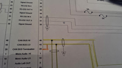
Here's what the wiring looks like:
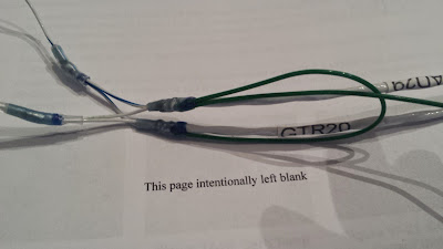
Obviously, I forgot to make a pin for the CAN bus termination (#48 pin), but is this the right idea? I used small solder sleeves for the node splices on the CAN bus, and big solder sleeves to carry the shield from the wire.
I'm not sure if I'm on the right track here, because I followed Derek's post and tied the two backbones together with a shield wire even though my diagram doesn't explicitly show that.
Anyway, is this the right way to do this? The point to point wiring was WAY easier!
Thanks
Chris
Update: Yup, thanks to Derek and Steve's earlier posts it is wired correctly. Except I should have used butt splices or heat shrink over a soldered joint to make the connection. Thanks for the help guys
I don't really understand the CAN bus wiring methods, perhaps I'm alone here.
Stein Air made my wiring diagram (thank goodness!) and the "ends"/"terminations" of the CAN bus are the GDU 460 (screen) and the GSA 28 (autopilot servo).
Update:The manual alludes to preferentially making the CAN terminations on the GAD 29, GSU 25,GEA 24, or the GSA 28. However the screen works just fine as a termination.
Anyway, I followed this thread and made a mock up. Here's the wiring diagram section:
Here's what the wiring looks like:
Obviously, I forgot to make a pin for the CAN bus termination (#48 pin), but is this the right idea? I used small solder sleeves for the node splices on the CAN bus, and big solder sleeves to carry the shield from the wire.
I'm not sure if I'm on the right track here, because I followed Derek's post and tied the two backbones together with a shield wire even though my diagram doesn't explicitly show that.
Anyway, is this the right way to do this? The point to point wiring was WAY easier!
Thanks
Chris
Update: Yup, thanks to Derek and Steve's earlier posts it is wired correctly. Except I should have used butt splices or heat shrink over a soldered joint to make the connection. Thanks for the help guys
Last edited:
Bill.Peyton
Well Known Member
The CAN bus splice you have prepared is correct, with the exception that you do not need the additional wire from the shield to the backshell of the connector. You are permitted to run a non shielded wire from the node, as long as the wires are kept under 2", which you have done. You only need the shield terminated at the backshell at each end of the total bus. Refer back to Steve's post earlier in this thread.
Brantel
Well Known Member
Can the ends of the canbus be at the pitch and roll servos and all the other devises connected inbetween ? Like the "trot line" with the servos on each end .
Yes........
Bill.Peyton
Well Known Member
Which ever servo is the last, or end servo, must have the resistive termination.
Roll Servo Node
With respect to the roll servo, if you are running the shielded CAN bus down the inside of the fuselage and then back to the pitch servo for termination, that means a node run of probably about 6 feet out to the roll servo. The Garmin manual indicates that node runs are to be no more than 1 meter. What are people doing to get around this limitation? Are you running the CAN bus shielded wire out and back in the wing? Does running a shielded node wire negate the 1 meter limit? I am going to be closing up the wings soon and would like to get the roll servo set with wires before riveting on the back skin. Thanks.
With respect to the roll servo, if you are running the shielded CAN bus down the inside of the fuselage and then back to the pitch servo for termination, that means a node run of probably about 6 feet out to the roll servo. The Garmin manual indicates that node runs are to be no more than 1 meter. What are people doing to get around this limitation? Are you running the CAN bus shielded wire out and back in the wing? Does running a shielded node wire negate the 1 meter limit? I am going to be closing up the wings soon and would like to get the roll servo set with wires before riveting on the back skin. Thanks.
Can bus node
If you are using the pitch servo as a Can Termination ( as I did on my 8 ) I ran the canbus (2/ shielded ) from the panel area to the roll servo then to the pitch servo . The "node " will only be the few inches of wire entering the roll servo backshell.
I found making almost all the harnesses at my desk at night was a lot more enjoyable than the hot Florida hangar .
Bill.Peyton
Well Known Member
Node runs are the unshielded, or shielded if the run is more than 2", but not more than 1 meter, portion of wire coming from the branch you create at each device. Running a shielded wire from the roll servo back to the pitch servo and creating a node at the pitch servo, then continued running of the shielded wire from the pitch servo forward to the next LRU meets the requirement of the IM node limitation.
Last edited:
Resurrecting this great thread...
The photo of the can bus splice below is exactly what I have been looking for, with one additional question. The splices look very clean, but I can't tell if they just joined three wire ends under the heat shrink, or did they carefully strip away a portion of insulation from the "middle" of one of the wires and the end of the other wire before soldering and covering with the heat shrink?
The photo of the can bus splice below is exactly what I have been looking for, with one additional question. The splices look very clean, but I can't tell if they just joined three wire ends under the heat shrink, or did they carefully strip away a portion of insulation from the "middle" of one of the wires and the end of the other wire before soldering and covering with the heat shrink?
Im no Expert (pun intended) but I think your wires labeled Hi/lo are the node and what they meant to say was to connect them to the CAN Bus. In this photo, the wire that my fingers are pinching is the CAN bus. This is a mockup of my CAN bus from the GEA 24 to the GSU 25 to the GAD 29 with the GAD 29 at the end of the bus. you could also look at this as being the AP servos to the Left and right of my fingers, with the servo to the right of my fingers, at the end of the bus. (someone please correct me if im wrong here) By the way, this is just another example of the service from Stein air, this mockup was provided with my wiring harness for the GAD 29, showing exactly how to tap into the CAN bus.
Walt
Well Known Member
I know folks do it different ways but solder sleeves are made for shield terminations, they are not designed nor should they be used to solder wires together.
The way I do it:
Prepare the two wires and terminate the shields with solder sleeves. Install the pins on one pair, use mil spec strippers to strip back the insulation (pushing the insulation toward to pin), solder by hand the other pair of wires at the junctions, install double wall adhesive lined heat shrink over the soldered splice joint. Be sure your splice is located so that it will not be under the backshell strain relief.
So if I understand this correctly if you are terminating at the servo you jumper pins #3 and #4 and you install a 120 ohm resistor at the end of the can bus?
Or you install a 120 ohm resister as jumper in pin #3 and #4?
Hello Adam,
Terminating the CAN bus at a GSA 28 servo is super easy because crimping two pins on a short wire and plugging these two pins into positions 3,4 on the servo connector enables an internal 120 ohm resistor across the end of the CAN bus. No external resistor needed.
Since your pitch and roll servos are located at the extreme ends of your CAN bus, both of your servos will have jumpers between pins 3,4 as shown on the roll and yaw servos in this wiring example from the G5 manual.

Thanks,
Steve
Last edited:
Thank you for the info Steve, I was hoping that was not the case, because I installed it as you described.
I am having a issue though, the roll servo LED is a steady green and the pitch LED is a steady red. The G5 under devises does not give a red "X" or green check mark for anything but the G5 which is green. Any suggestions.
G5 - 307 - roll and pitch servos.
Check connections and I am not finding a problem.
Thanks for the help!
Thank you for the info Steve, I was hoping that was not the case, because I installed it as you described.
I am having a issue though, the roll servo LED is a steady green and the pitch LED is a steady red. The G5 under devises does not give a red "X" or green check mark for anything but the G5 which is green. Any suggestions.
G5 - 307 - roll and pitch servos.
Check connections and I am not finding a problem.
Thanks for the help!
Hello Adam,
Please check the G3Xpert email sent several hours ago for suggestions.
Thanks,
Steve

