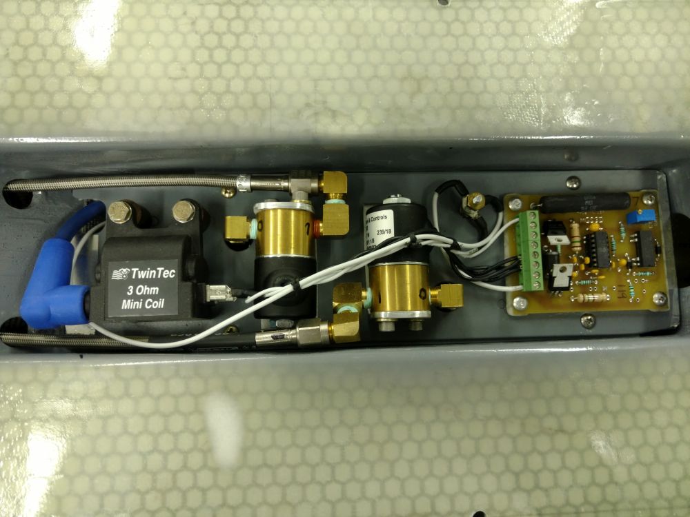
The first of two related under-wing projects is a gas gun, aka a "machine gun simulator" in the military reenactor and movie prop worlds. The basic operating principle is simple enough. A timer board controls two solenoid valves and an ignition coil. Oxygen and propane are vented into a chamber, the solenoids close, the coil fires, and the result is a shock wave at the tip of the barrel. There is no projectile, just noise and muzzle flash.
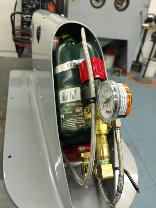
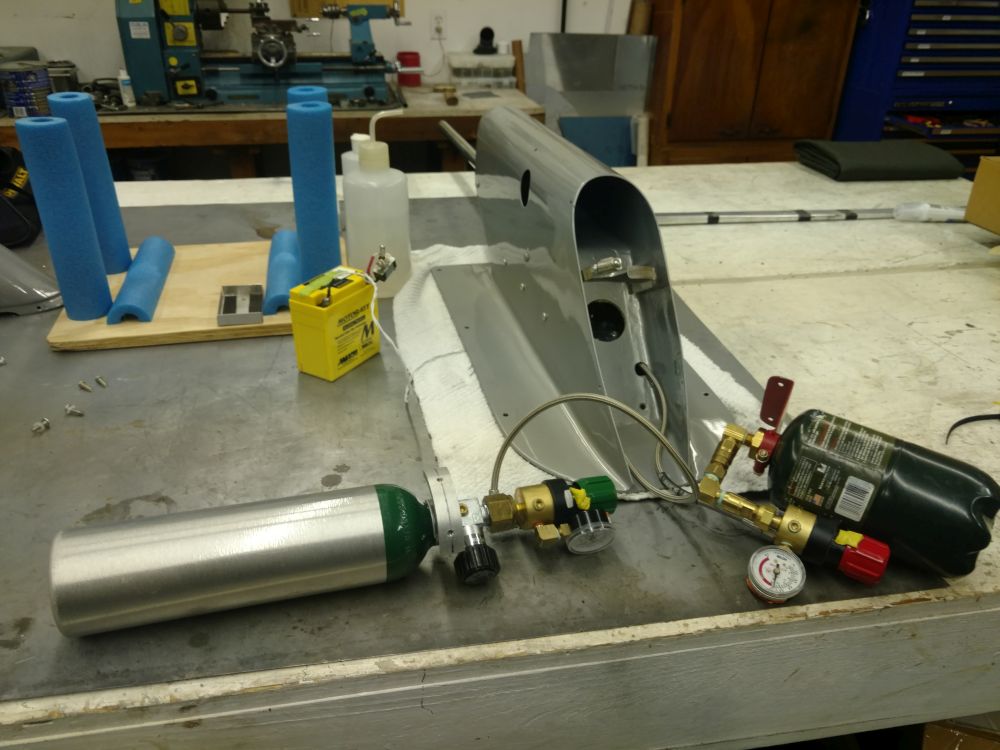
Propane supply is typically one of the standard 1 lb, 4" dia bottles from the camping department. Overall, they are low pressure canisters full of liquid, with actual pressure linked to temperature. High pressure oxygen is a bit more involved. The bottle is charged to 2000 psi, just like breathing oxygen. In this case, I selected a new M6 size bottle, 3.2" dia and 11" long, plus valve.
The regulators are new Victor G150's, modified by changing some of the fittings, plus removing the high pressure gauge and plugging the port. The gas regulator requires an adapter between the propane bottle and the regulator inlet. The propane bottle must be upright so only vapor reaches the outlet; liquid propane shuts down the gun, as the mixture is too rich. I found a 45 degree bottle angle was practical, then assembled fittings and a 1/4 turn valve so as to put the regulator alongside the bottle, inside the taper of the aeroshell's tail.
The O2 bottle can be ordered with a CGA-540 outlet valve so it will couple directly to the Victor regulator. The required transfill hose has male CGA-540 fittings at both ends fill the bottle from a shop oxygen tank.
The timer board, solenoids, and some other detail parts were sourced from Steve Smith (No, not our Steve Smith. A different one. Apparently there are a lot of them.) Go here: http://www.ww2steel.com/Gasguns/Gasguns.html
So, how to package the above? I started with CAD drawings, moving key bits around to consider the effects on packaging, aero, and structure. In the end, the best configuration was a 4" wide enclosure laid out as three stacked compartments:
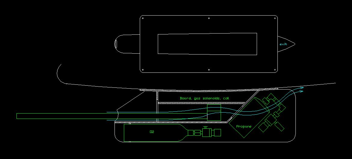
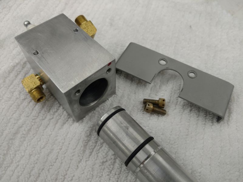
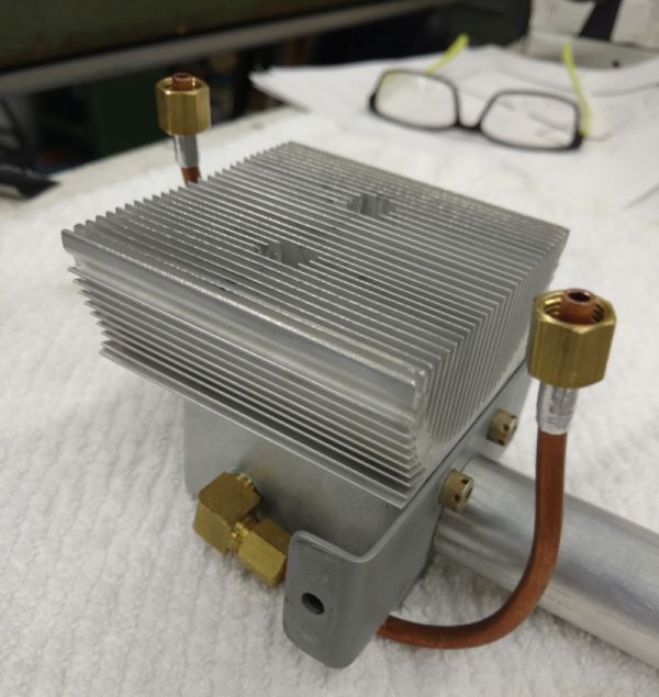
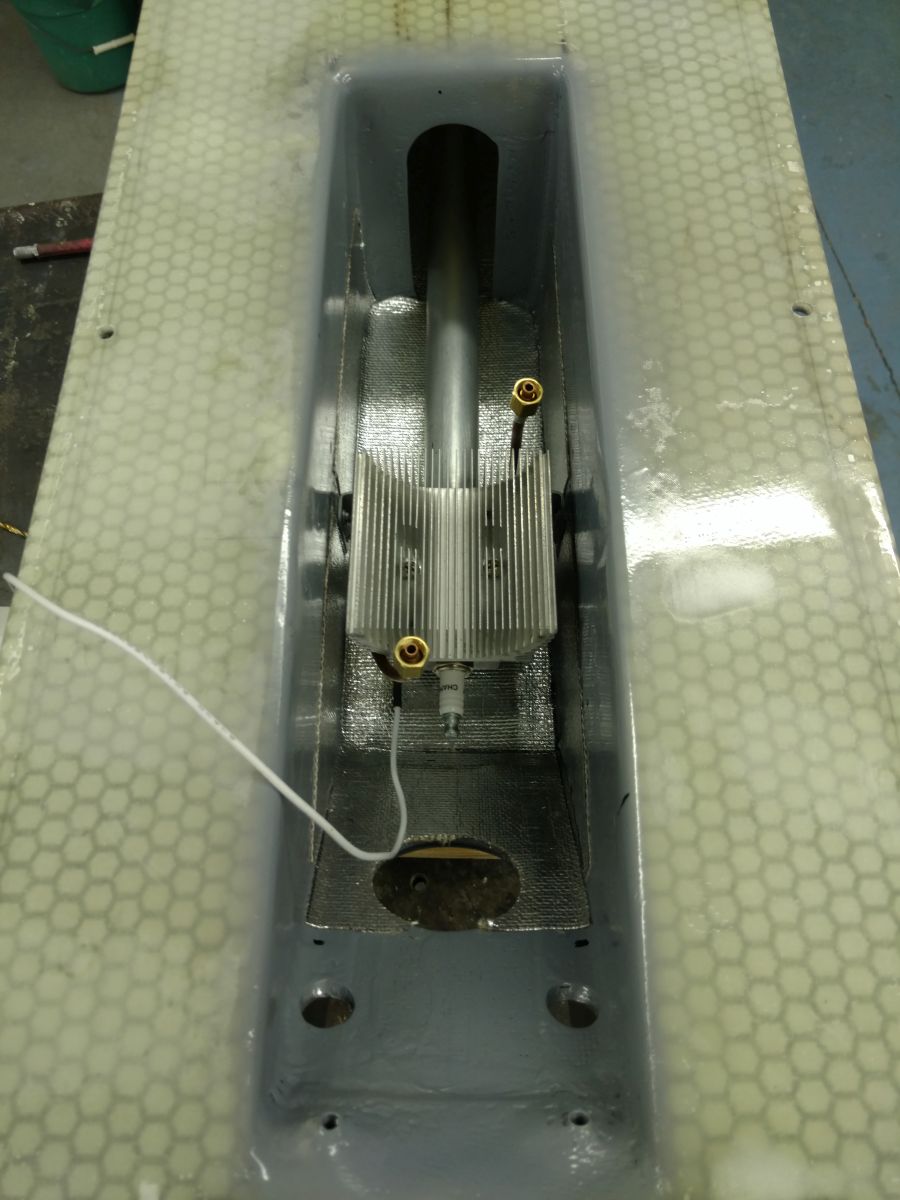
The O2 bottle is in the belly, with the butt end extending through a support bulkhead, and the valve end supported by a custom aluminum fitting. The gun compartment has an annular air intake. Cooling air (cyan) flows along the barrel, past a breech block with a heat sink, through a rear bulkhead, then around the propane bottle and out an exit at the underside of the wing. The flow cools the gun and warms the bottle, good for both. The entire compartment is lined with aluminized insulation, although it's probably not needed. The upper compartment contains the board, solenoids, and the ignition coil.
Structure is a glass/epoxy shell with internal bulkheads. The bulkheads and the mounting plate are 2mm Lanter Soric cores with glass face plies. The uppermost floor is a bolt in, allowing access to the gun compartment. The tail comes off for bottle service.
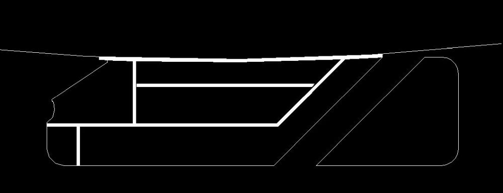
The base shell was created with 4 plies of 9oz BID laid up over a solid foam block. As always, time spent making good forms and molds pays a large dividend later.
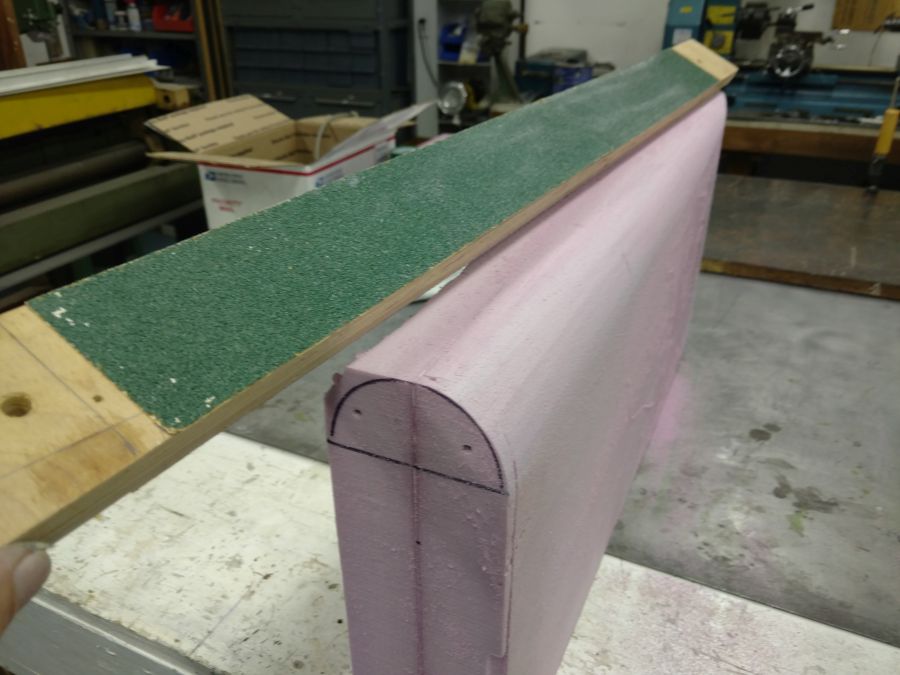
Gotta start somewhere. Draw guidelines and rough it out:
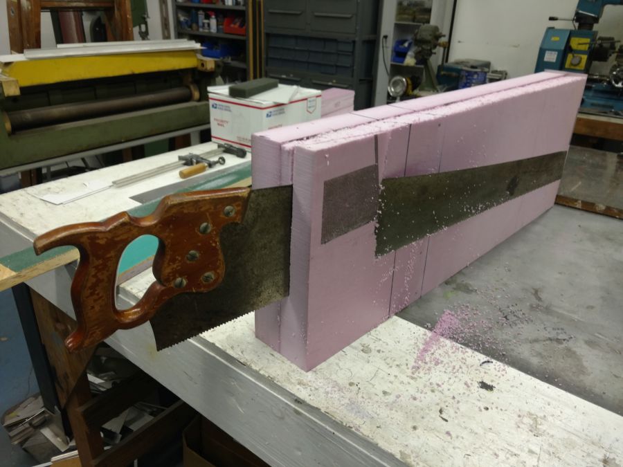
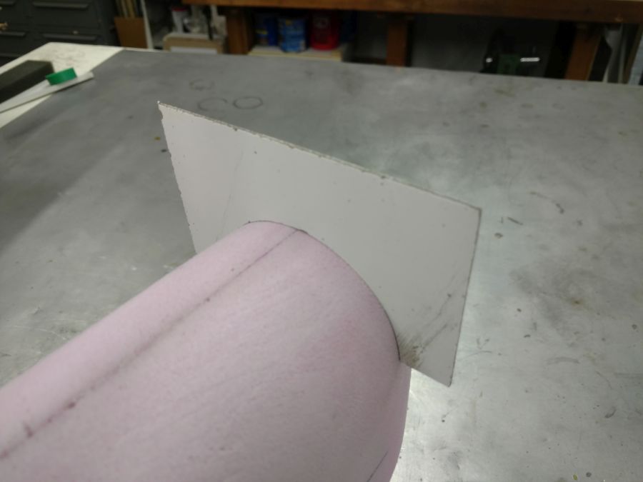
Shape with 80 grit blocks and templates:
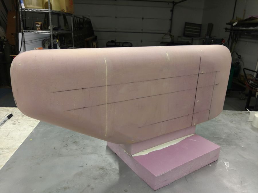
The shaped block was epoxy coated for sealing, lightly sanded, waxed twice, and sprayed with PVA. Here it is, ready for layup:
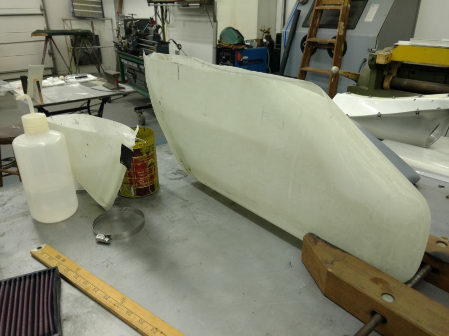
The base is temporary. It was cut off. The stacked BID plies were wet out between plastic sheets, draped and smoothed over the form, then covered in peel ply and bleeder ply. The whole thing went into a plastic bag, where it was placed under vacuum for cure. After cure, it was cut into two parts. A few hits with compressed air and the form popped right out, leaving the raw shells.
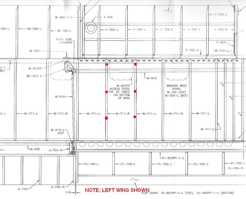
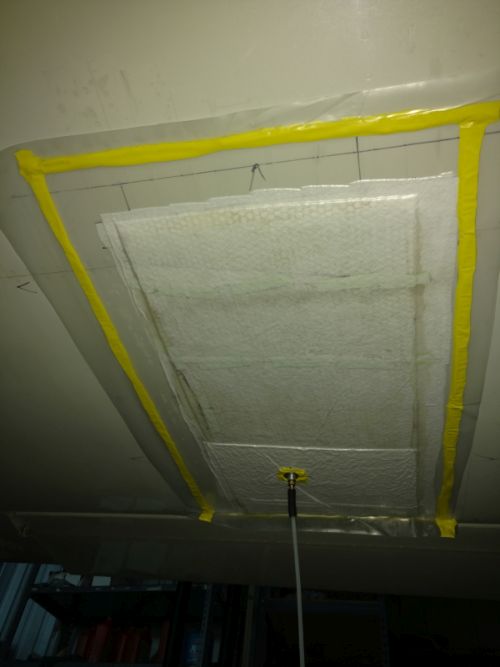
The cored bulkheads were cut from flat layups cured on the bench. They were bonded in with flox filets and 2 ply layups. The mount plate was molded right on the bottom of the wing to ensure a matched curve. The wing was protected with gloss tape. The layup position was drawn on the tape. The wetted, stacked layup (bleeder ply, peel ply, glass plies, soric core, glass plies, peel ply) was positioned and covered with a 4 mil plastic sheet, the perimeter of which sealed to the wing with sticky tape. Vacuum ensured conformance.
Determining the correct alignments required some jigging on the wing, while trimming the shell to match the mount plate curve. When it was right, the shell was tacked to the plate with a few dots of five minute epoxy, then taken home for the connecting layups.
More later.
Propane supply is typically one of the standard 1 lb, 4" dia bottles from the camping department. Overall, they are low pressure canisters full of liquid, with actual pressure linked to temperature. High pressure oxygen is a bit more involved. The bottle is charged to 2000 psi, just like breathing oxygen. In this case, I selected a new M6 size bottle, 3.2" dia and 11" long, plus valve.
The regulators are new Victor G150's, modified by changing some of the fittings, plus removing the high pressure gauge and plugging the port. The gas regulator requires an adapter between the propane bottle and the regulator inlet. The propane bottle must be upright so only vapor reaches the outlet; liquid propane shuts down the gun, as the mixture is too rich. I found a 45 degree bottle angle was practical, then assembled fittings and a 1/4 turn valve so as to put the regulator alongside the bottle, inside the taper of the aeroshell's tail.
The O2 bottle can be ordered with a CGA-540 outlet valve so it will couple directly to the Victor regulator. The required transfill hose has male CGA-540 fittings at both ends fill the bottle from a shop oxygen tank.
The timer board, solenoids, and some other detail parts were sourced from Steve Smith (No, not our Steve Smith. A different one. Apparently there are a lot of them.) Go here: http://www.ww2steel.com/Gasguns/Gasguns.html
So, how to package the above? I started with CAD drawings, moving key bits around to consider the effects on packaging, aero, and structure. In the end, the best configuration was a 4" wide enclosure laid out as three stacked compartments:
The O2 bottle is in the belly, with the butt end extending through a support bulkhead, and the valve end supported by a custom aluminum fitting. The gun compartment has an annular air intake. Cooling air (cyan) flows along the barrel, past a breech block with a heat sink, through a rear bulkhead, then around the propane bottle and out an exit at the underside of the wing. The flow cools the gun and warms the bottle, good for both. The entire compartment is lined with aluminized insulation, although it's probably not needed. The upper compartment contains the board, solenoids, and the ignition coil.
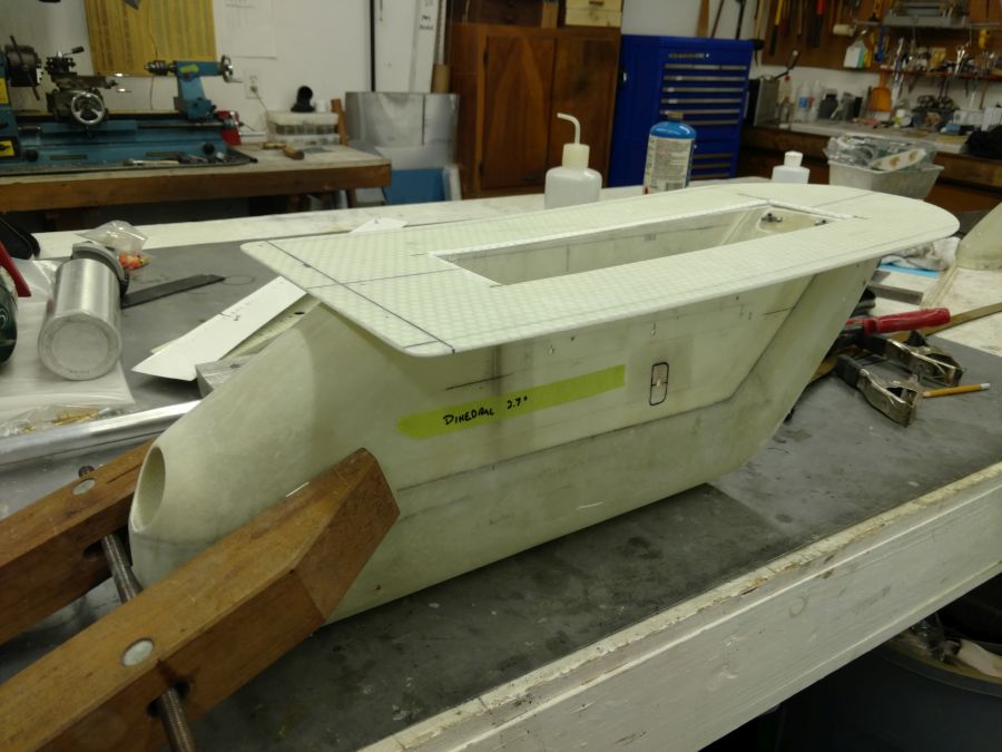
Structure is a glass/epoxy shell with internal bulkheads. The bulkheads and the mounting plate are 2mm Lanter Soric cores with glass face plies. The uppermost floor is a bolt in, allowing access to the gun compartment. The tail comes off for bottle service.
The base shell was created with 4 plies of 9oz BID laid up over a solid foam block. As always, time spent making good forms and molds pays a large dividend later.
Gotta start somewhere. Draw guidelines and rough it out:
Shape with 80 grit blocks and templates:
The shaped block was epoxy coated for sealing, lightly sanded, waxed twice, and sprayed with PVA. Here it is, ready for layup:
The base is temporary. It was cut off. The stacked BID plies were wet out between plastic sheets, draped and smoothed over the form, then covered in peel ply and bleeder ply. The whole thing went into a plastic bag, where it was placed under vacuum for cure. After cure, it was cut into two parts. A few hits with compressed air and the form popped right out, leaving the raw shells.
The cored bulkheads were cut from flat layups cured on the bench. They were bonded in with flox filets and 2 ply layups. The mount plate was molded right on the bottom of the wing to ensure a matched curve. The wing was protected with gloss tape. The layup position was drawn on the tape. The wetted, stacked layup (bleeder ply, peel ply, glass plies, soric core, glass plies, peel ply) was positioned and covered with a 4 mil plastic sheet, the perimeter of which sealed to the wing with sticky tape. Vacuum ensured conformance.
Determining the correct alignments required some jigging on the wing, while trimming the shell to match the mount plate curve. When it was right, the shell was tacked to the plate with a few dots of five minute epoxy, then taken home for the connecting layups.
More later.
Last edited:
")