I'm working on wiring for the Garmin GAD 27 and have some questions about how power goes in and out related to the trim servos.
First, some basics. There are two power inputs so the GAD 27 can be powered from two separate busses -- J271 pin 7 and TB273 pin 1. Technically the latter is for the "keep alive" feature but the manual says it can also power the GAD 27.
Second, the lights (presumably landing/tax) are easy -- light 1 power in, light 2 power in, light 1 power out, light 2 power out. The flaps are just as easy -- flap power in, flap power out (there is also a flap power ground, but no ground for the lights).
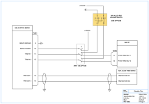
Now my assumptions about trim -- there are inputs for PITCH TRIM POWER IN, PITCH TRIM POWER GND, ROLL TRIM POWER IN, and ROLL TRIM POWER GND. As I understand it, if you are using the GSA 28s for autopilot, and if you want autotrim, you should connect the trim motors to those units, and then you connect ROLL TRIM OUT 1/2 and PITCH TRIM OUT 1/2 from the GAD 27 to the appropriate GSA 28. It also seems that, in normal situations, not much power flows from the GAD 27 to the GSA 28s -- the actual power for the trim motors comes directly from the GSA 28s, and the connection from the GAD 27 is just a signal.
Finally, I have this information from @g3xpert about how/when the GAD 27 does directly power the trim motors:
So, here is my actual question -- how do I wire two pullable circuit breakers -- one that can disable autopilot and a second one that can disable the trim servos?
I think Autopilot is easy -- I can have a single circuit breaker and wire all of the GSA 28s through that breaker. If that breaker is pulled, the trim system will work as described in the quote above.
Now how do I disable the trim system through a circuit breaker? If I interrupt PITCH TRIM POWER IN and ROLL TRIM POWER IN into the GAD 27, will that prevent it from passing along any signals to the GSA 28s regarding trim? Even though the trim is actually being powered by the GSA 28s? I'm looking for a quick way to disable both the pitch and roll trim servos quickly in a runaway situation. Pulling a breaker to disable the GAD 27 is not ideal since it does other things as well, and since I'll be using two power inputs.
First, some basics. There are two power inputs so the GAD 27 can be powered from two separate busses -- J271 pin 7 and TB273 pin 1. Technically the latter is for the "keep alive" feature but the manual says it can also power the GAD 27.
Second, the lights (presumably landing/tax) are easy -- light 1 power in, light 2 power in, light 1 power out, light 2 power out. The flaps are just as easy -- flap power in, flap power out (there is also a flap power ground, but no ground for the lights).
Now my assumptions about trim -- there are inputs for PITCH TRIM POWER IN, PITCH TRIM POWER GND, ROLL TRIM POWER IN, and ROLL TRIM POWER GND. As I understand it, if you are using the GSA 28s for autopilot, and if you want autotrim, you should connect the trim motors to those units, and then you connect ROLL TRIM OUT 1/2 and PITCH TRIM OUT 1/2 from the GAD 27 to the appropriate GSA 28. It also seems that, in normal situations, not much power flows from the GAD 27 to the GSA 28s -- the actual power for the trim motors comes directly from the GSA 28s, and the connection from the GAD 27 is just a signal.
Finally, I have this information from @g3xpert about how/when the GAD 27 does directly power the trim motors:
In normal operation the GSA 28 servos are always powered-up, and even when the autopilot is disengaged, the servos are providing speed scheduled variable voltage to the trim motors independent of the GAD 27. The GAD 27 is only providing trim direction signals to pins 11,12 of the GSA 28 the majority of the time.
It is only when the GSA 28 is powered off (a trim bypass relay drops) and non speed scheduled direct drive power is being supplied by the GAD 27 to the trim motor does the size of the GAD 27 trim power circuit breaker make any difference.
So, here is my actual question -- how do I wire two pullable circuit breakers -- one that can disable autopilot and a second one that can disable the trim servos?
I think Autopilot is easy -- I can have a single circuit breaker and wire all of the GSA 28s through that breaker. If that breaker is pulled, the trim system will work as described in the quote above.
Now how do I disable the trim system through a circuit breaker? If I interrupt PITCH TRIM POWER IN and ROLL TRIM POWER IN into the GAD 27, will that prevent it from passing along any signals to the GSA 28s regarding trim? Even though the trim is actually being powered by the GSA 28s? I'm looking for a quick way to disable both the pitch and roll trim servos quickly in a runaway situation. Pulling a breaker to disable the GAD 27 is not ideal since it does other things as well, and since I'll be using two power inputs.


