Van's Air Force

The definitive Van's Aircraft support community! Buying, building or flying an RV? Join our exclusive family of mentors and enthusiasts!

G3X roll servo

FlyingDutchman257

Active Member
Hello all,

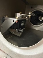
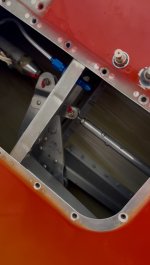
Has anyone put the G3X roll servo in the wing? If so, do you have any photos available?

What is the experience from those having the roll servo near the stick? Do you induce a pitch moment?

Many thanks in advance
Marcel
 
On my -6, I mounted it in the wing, just inboard of the tip to the back of the spar web. Haven’t flown it yet but it was an easy install. It did require an aftermarket 90° backshell for the servo connector.
 

Attachments

  • IMG_1042.jpeg
    IMG_1042.jpeg
    1.6 MB · Views: 83
  • IMG_1050.jpeg
    IMG_1050.jpeg
    339.4 KB · Views: 81
On my -6, I mounted it in the wing, just inboard of the tip to the back of the spar web. Haven’t flown it yet but it was an easy install. It did require an aftermarket 90° backshell for the servo connector.
The bellcrank on the -6 looks very similar to the one on the -4, if not exactly the same. I like your set up.
 
If you don’t have foot wells for the rear pax you can mount it just aft of an aileron pushrod under where a well would be. The servo pushrod attaches to the torque tube at the same point as the aileron pushrod. Just need a longer attach bolt.
 
If you don’t have foot wells for the rear pax you can mount it just aft of an aileron pushrod under where a well would be. The servo pushrod attaches to the torque tube at the same point as the aileron pushrod. Just need a longer attach bolt.
Have you actually tried this? do the geometrics match? My gut feeling says that the throw on the stick is bigger than the throw on the servo.
 
Have you actually tried this? do the geometrics match? My gut feeling says that the throw on the stick is bigger than the throw on the servo.
The kinematics do work. The control column movement isn't that much and the actuator throws are adjustable. I believe this particular one is the TruTrak approach. Drawings were available from download from their site before it was sold to Bendix; might still be there. I've seen it adopted on a Grand Champion Rocket (sample pic below).

That said:
- because of the geometry, the force required from the servo is not the same in both roll directions. A fact but does not seem to affect control.
- control systems tend to work better when the entire range of an actuator/servo/etc. is utilized versus something less.

Future maintenance considerations kept me from the wing bell crank approach. Personal preference for the type of fabrication involved is why I chose the connection point near the front stick like FinnFlyer IIRC and others e.g. fab'ing an attach bracket (second pic below) versus a welded or banded/staked bearing attach point.

Both control column approaches and the wing bell crank approach have been "validated". This affords you the opportunity to not overthink. My advice, which counts for nothing, would be to stand on the shoulders of previous, successful builders and pick the approach where you're the most comfortable with the fabrication involved. You have (at least) three proven approaches.

Screen Shot 2020-09-16 at 7.59.42 AM.png
screen shot.jpg
 
Thanks Freemasm for posting the pix.
The advice to not reinvent the wheel is spot on.
To clarify my experience:
I didn’t have room to mount so as to actuate at the base of the stick.
My -4 has no foot wells. I used the aileron pushrod attach actuation position.
In my Rocket I have foot wells so I went with the further aft mounted position that uses the actuation position attached directly to a circular clamp on the torque tube.
These 3 locations seem to be the most common approaches.
 
Last edited:
Thanks Freemasm for posting the pix.
The advice to not reinvent the wheel is spot on.
To clarify my experience:
I didn’t have room to mount so as to actuate at the base of the stick.
My -4 has no foot wells. I used the aileron pushrod attach actuation position.
In my Rocket I have foot wells so I went with the further aft mounted position that uses the actuation position attached directly to a circular clamp on the torque tube.
These 3 locations seem to be the most common approaches.
I looked very hard at the shared push-tube attach point approach. It didn't afford the mechanical advantage of the others; ideally you'd want the two attach points in different (geometric) planes where the actuator linkage would be at 90's at both attach points. This would take less power/afford more equivalent force from the actuator. As the Garmin actuators only draw 1.8 amps, I was afraid of the servo/torque motor could possibly stall. Very elegant solution but I didn't know of an aircraft actually flying with that configuration at the time I was descending into that rabbit hole. Zero other builders at Orlando Executive. If you've adopted this and it's proven itself then it's another option after footwell, push-tubes, and ventilation/heating ducts are considered.
 
- because of the geometry, the force required from the servo is not the same in both roll directions. A fact but does not seem to affect control.
Just a general note for installations where this condition exists... When you are configuring the torque limits for a servo, you're trying to find the highest torque setting where the pilot can still physically overpower the servo in an emergency. If the geometry of your control system is asymmetrical in this way, it's worth testing the overpower force in both directions to make sure.
 
Back
Top