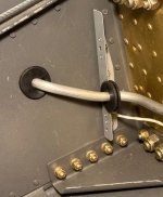
Has anyone found that they need additional holes to send the fuel gauge sending wire from the cockpit to the tanks?
If so, where did you put the new hole?
I ran out of "hole" space and was just wondering.
Daddyman
If so, where did you put the new hole?
I ran out of "hole" space and was just wondering.
Daddyman