DaleB
Well Known Member
When I feel tempted to chuck a tool or part across the garage, I know it's time to quit for the day.
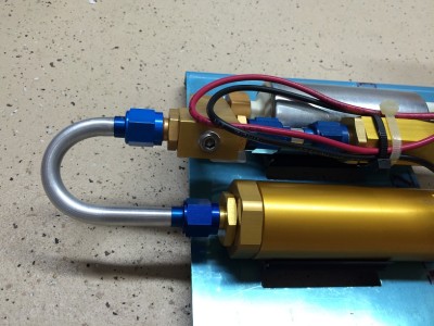
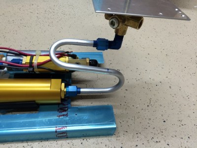
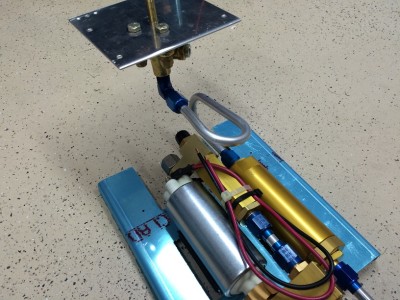
I spent a couple of hours this afternoon trying to plumb the fuel filter and fuel pump (the new style AFP FI boost pump & filter package). All I managed to do was create a few more feet of scrap aluminum tubing for the trash can. My bends are OK, my flares are OK, but getting the right length is proving to be a real challenge. Is there a secret to measuring so these things come out the right length? Or do I just keep trying until I luck into it?
I also wonder about the layout. I see the Van's diagram for the old style pump has the supply line running from the selector valve underneath the pump & filter, into the forward end of the filter. From there they show a run from the aft end of the filter to the forward end of the pump assembly, and from the aft end of the pump down underneath again to run forward toward the firewall. With the new style pump it seems like it would be a lot easier and use a lot less tubing to just put the output of the filter and the input of the pump on the same end, connected with a short tube with two 90 degree bends (or a big 180) instead of a foot long piece with two 180 bends. A guy could even just use a short L-shaped tube from the fuel selector to the filter input. Does that make sense, or would it be likely to cause a problem with cracking due to vibration and stress? I haven't seen anything showing the routing of fuel lines with the new style boost pump that doesn't need all of the extra plumbing.