Van's Air Force

The definitive Van's Aircraft support community! Buying, building or flying an RV? Join our exclusive family of mentors and enthusiasts!

Flush pop rivets on the wing rear spar doublers

ymc9

Well Known Member
Patron
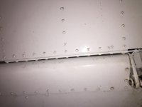
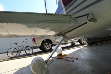
The wing KAI section 14-03 asks to countersink the lower side holes of the rear spar doublers and install flush pop rivets (marked with the red rectangle below). Although it's easy to do, I'm curious about the reason for making this specific part flush. Is it for clearance when attaching the flaperons? Also the hole I marked with the blue arrow is stranger - the hinge sits above the doubler so it's not flush anyway, what's the point of making that hole flush ...?

Screenshot at Mar 16 09-36-51.png
 
The original plans called those rivets out as LP$=3 but it was found that the flaperon was very close or even touched when depressed; see picture. I don't think it resulted in a service bulletin or letter but posts on VAF led me to retrofit the flush rivets about 9 years ago on my wings. Not hard to do.
 

Attachments

  • IMG_3372.jpeg
    IMG_3372.jpeg
    1.4 MB · Views: 115
  • P1060411.jpeg
    P1060411.jpeg
    4.1 MB · Views: 113
The original plans called those rivets out as LP$=3 but it was found that the flaperon was very close or even touched when depressed; see picture. I don't think it resulted in a service bulletin or letter but posts on VAF led me to retrofit the flush rivets about 9 years ago on my wings. Not hard to do.
Thank you, sir! It all makes sense now. I guess I'll have to grind my countersink cage now otherwise it won't fit into the hinge corner hole.
 
Thank you, sir! It all makes sense now. I guess I'll have to grind my countersink cage now otherwise it won't fit into the hinge corner hole.
Not necessary

For a single case situation such as this, an acceptable job can be done with the piloted counter sink cutter installed in a deburring tool shaft and turned slow with a cordless drill.
Just go slow and check the depth often with a rivet.
If you haven't put primer on the bracket, use the reflection to confirm vertical alignment (horizontal alignment can be checked by confirming your parallel to the arm of the bracket. If the part has primer on it, use a small square to install a piece of tape square to the flange to use as a reference in the vertical direction.
Got it. I'll give it a try. Thank you for the tips!
 
Hi. I add my concurrence to installing the CS4-4 as depicted in the most current version of the plan on the lower side of the doubler. The clearance is tight when the Flaperons are taken to the stop. When you paint, if you have a base layer, main layer and clear coat, you may find a few LP4 rivets are too high and you need to remove the clear coat. I know. That is tight. Non the less I have seen that actual condition. There is also some confusion in the maint manual over using LP4. CS4-4 is the choice for me on that lower line on the doubler (as specified in the most current plan). Best of luck
 
If anyone has done this on a completed airplane, can you tell me if I'm going to need to remove the flaperons to get access to these rivets? Or can I do this with the flaperons still installed on the wing?
 
Back
Top