
Van's Air Force
You are using an out of date browser. It may not display this or other websites correctly.
You should upgrade or use an alternative browser.
You should upgrade or use an alternative browser.
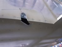
Flap extension rod exits
- Thread starter daddyman
- Start date

")


I just did this step a few months ago on my -6 build.
I think the best way to lay this hole out is to put the flaps on and mark directly. You can see from the pictures above that the bolt/spacer for the Heim joint is going to go up into the side skin. You can swing the flap up until contact and mark the position and width, and measure the height of the notch. You can also mark the width and depth of the Heim on the bottom skin. I drilled a hole, enlarged with a step drill, then opened it up with a rotary tool to the lines. Then fit the linkage rod and make additional trims for clearance through the travel. Mark the flap overlap on the fuselage to avoid going past as you will have an uncovered hole if you do.
I think the best way to lay this hole out is to put the flaps on and mark directly. You can see from the pictures above that the bolt/spacer for the Heim joint is going to go up into the side skin. You can swing the flap up until contact and mark the position and width, and measure the height of the notch. You can also mark the width and depth of the Heim on the bottom skin. I drilled a hole, enlarged with a step drill, then opened it up with a rotary tool to the lines. Then fit the linkage rod and make additional trims for clearance through the travel. Mark the flap overlap on the fuselage to avoid going past as you will have an uncovered hole if you do.
Desert Rat
Well Known Member
The issue is that as the flaps go up and down, the rod not only goes fwd/aft, but also moves outboard/inboard. The hole ends up being this weird ellipse shape. Picture an oval thats partially on the belly and partially on the side.
I hooked the flaps up one at a time and moved them by hand. every time it rubbed I marked with a sharpie, took the rod back out and hit it with a file. The holes will end up being bigger than you would guess at first glance.
I hooked the flaps up one at a time and moved them by hand. every time it rubbed I marked with a sharpie, took the rod back out and hit it with a file. The holes will end up being bigger than you would guess at first glance.
The issue is that as the flaps go up and down, the rod not only goes fwd/aft, but also moves outboard/inboard. The hole ends up being this weird ellipse shape. Picture an oval thats partially on the belly and partially on the side.
I hooked the flaps up one at a time and moved them by hand. every time it rubbed I marked with a sharpie, took the rod back out and hit it with a file. The holes will end up being bigger than you would guess at first glance.
Same here.
Looked like ugly duckling egg when finished.
By Hand is easiest way.
Boomer
daddyman
Well Known Member
thanks to all
Big help.
Especially for the pictures.
Daddyman
You may not want to drill into the side skin, but you’re going to have to. The good news is the flap pushrod hole gets covered up when the flaps are up. Good for 10kts….at least.
Here’s pictures of mine.
View attachment 49106
View attachment 49107
Big help.
Especially for the pictures.
Daddyman
Scott Hersha
Well Known Member
The rod bearing attachment to the flap in post #2 is non-standard, although probably preferable to protect flap rod attachment in the case of a bearing failure. Plans built lower rod bearing attach:
https://www.aircraftspruce.com/catalog/appages/auroracm.php?clickkey=3009380
If the bearing fails in the one above, it could possibly slip off the ball, allowing that flap to retract, although I’ve never heard of that happening, and it’s the one I used. I wasn’t wise enough to consider this post 2 attachment when I was building my -6.
Stevea
Well Known Member
The rod bearing attachment to the flap in post #2 is non-standard, although probably preferable to protect flap rod attachment in the case of a bearing failure. Plans built lower rod bearing attach:
https://www.aircraftspruce.com/catalog/appages/auroracm.php?clickkey=3009380
If the bearing fails in the one above, it could possibly slip off the ball, allowing that flap to retract, although I’ve never heard of that happening, and it’s the one I used. I wasn’t wise enough to consider this post 2 attachment when I was building my -6.
True, mine is a “non-standard” hardware setup. In other words, not the part selected by Van’s. I had the original design parts in there to start with. Only reason I changed them out was comments from my DAR about the rod end not being captured by a washer, like every other rod end connection in the RV (or at least how they are supposed to be assembled). After flying with the Van’s design for a while, I decided to see if it could be changed to the usual bolt and capture washer setup. Well, clearly the answer is yes. Been that way ever since.
BTW, the DAR couldn’t recall any failures of the original Van’s design…just didn’t like it as much as the “standard” design.
One other non standard part. The pushrod is a larger OD than called out by Van’s. This leaves more wall thickness after tapping for the rod ends. Reason: I didn’t like how thin the pushrod wall looked after thread tapping. (Yea, I know about the hex pushrods now offers. But those are way overkill for the 6 where the pushrod tubes are under 5” length and the pushrod buckling isn’t likely.)
Last edited:

