What's new
Van's Air Force

Don't miss anything! Register now for full access to the definitive RV support community.

Empennage Fairing

wirejock

Well Known Member
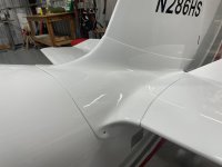
The Vans fairing isn't perfect, but most of it is usable by cutting the flanges that fit on top of the HS. I will adjust them to fit then reattach them. That leaves the bottom fairing. Sorry Vans. I can do better than a strip of aluminum angle.
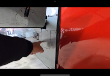
Sweetie is a Potter. I've worked a lot of clay. Laying up a clay mold seemed the easiest. I taped everything off and applied a wedge of kids modeling clay in the corner from leading edge to trailing edge. Then I shaped it using a 2" hunk of PVC for the radius and a spray bottle with water. Easy peasy. It's not reusable, but only took a couple hours to tape and layup both molds. It needs to dry enough to apply more tape then I can layup the bottom fairing. <fingers crossed
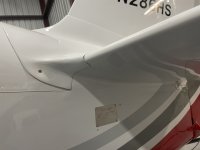
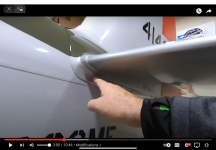
>20240112_155318.jpg
 
Is the Van's lower fairing on the -7 definitely made out of angle? On my -6A it is a just flat strip that is trimmed to match the profile of the HS. It is optional to put on a piece of rubber molding, otherwise there is a gap of 1/32". The plans show that the strip gets attached with #6 screws tapped into the longeron. I doubt that there will ever be a need to remove the lower fairing and I have seen some builders who just used pulled rivets.

How are you planning to attach your new fiberglass molded lower fairing?

DanH had a post about making a fiberglass lower fairing and I recall it was simply a small right angle moulded directly to the fuselage and HS with some packaging tape underneath and no clay or foam buildup. I think it was posted in the sticky in the fiberglass forum.
 
I’ve worked on some that fit well and some that didn’t. On my -8A the fit was one of the worst I’ve seen. I ended up cutting slits in it then screwing it in place. At that point I fiberglassed the gaps.
 
Is the Van's lower fairing on the -7 definitely made out of angle? On my -6A it is a just flat strip that is trimmed to match the profile of the HS. It is optional to put on a piece of rubber molding, otherwise there is a gap of 1/32". The plans show that the strip gets attached with #6 screws tapped into the longeron. I doubt that there will ever be a need to remove the lower fairing and I have seen some builders who just used pulled rivets.

How are you planning to attach your new fiberglass molded lower fairing?

DanH had a post about making a fiberglass lower fairing and I recall it was simply a small right angle moulded directly to the fuselage and HS with some packaging tape underneath and no clay or foam buildup. I think it was posted in the sticky in the fiberglass forum.
You are correct. It's a strip. I haven't decided yet, but Dan shared pictures of his and I like the design. If it fits correctly, there's less need for lots of fasteners. First step is fairings that fit.
 
You are correct. It's a strip. I haven't decided yet, but Dan shared pictures of his and I like the design. If it fits correctly, there's less need for lots of fasteners. First step is fairings that fit.
Agreed. The upper empennage fairing in my kit was a poor fit all around and it was easier to abandon it and make a new one. That took a fair bit of time and effort and succeeded on the third mold attempt, using sheet metal to lay up the fiberglass.

20220809_110633.jpg20220817_120018.jpg20240113_105833.jpg
 
Turns out vinyl backer paper is good for something else. It makes great mask.
By the way, clay works great till it starts to dry. Gravity! I managed to secure the clay mold before it fell off.
20240113_122040.jpg
 
Last edited:
……. Laying up a clay mold seemed the easiest. I taped everything off and applied a wedge of kids modeling clay in the corner from leading edge to trailing edge. Then I shaped it using a 2" hunk of PVC for the radius … <fingers crossed>View attachment 53861
If ‘pretty’ is the goal instead of speed cleanup, the radius of your mould will accomplish that. The 1” radius curve at the trailing edge will add to the turbulent flow behind the spar trailing edge.
I addressed this fairing on Race 57 (Rocket) with a fairly tight radius and followed up with a cleanup of the inner elevator edges (ribs) with faired caps that hopefully helped reduce the turbulent flow between the elevator inside edges & Rudder. This and a bunch of other fairing treatments gave #57 a 10 mph boost even before I got into the crazy engine & induction mods.
Once again, my OCD makes it slower. Oh bother
 
Once again, my OCD makes it slower. Oh bother
Apart from what Ralph said, also think about where the mounting screw holes would go. The 1 inch radius would likely place them below the longeron on the fuselage, so that could result in plate nuts in the side skins. The fairing, because of the width, would probably need to be fixed to the underside of the HS and those screw holes will land in the skin outboard of the root rib.
 
Apart from what Ralph said, also think about where the mounting screw holes would go. The 1 inch radius would likely place them below the longeron on the fuselage, so that could result in plate nuts in the side skins. The fairing, because of the width, would probably need to be fixed to the underside of the HS and those screw holes will land in the skin outboard of the root rib.
I've considered it. I haven't gotten that far.
 
Years ago, I used the "Gil Alexander" method. Waxed/Mold release on the fairing provided by Van's. A single layup of a light satin weave glass cloth and peel ply. Once the layup was cured, peel ply removed, wax / mod release on the tail of the airplane then double sided sticky tape to hold the stain weave layup on the airplane and lay up glass cloth to make a custom fairing.

The finished fairing has been held on my airplane with four screws since first flight back in 1997.
 
We don't need no stinkin' clay...

Seriously, no significant radius needed here.


Emp Fairing Lower.jpg
 
Last edited:
Fairings Etc… provides an excellent fitting fairing that takes minimal if any rework to make fit for those that don’t want to roll your own.
Not to take away from those that want to do it themselves.
 
I’ve used the Fairings etc lower empennage fairing on 3 of the 4 RV’s I’ve built It’s a very reasonably priced part and fits well on RV4, 6, and 8, and has a smal radius. On all of mine I just glued it right to the airframe using a flexible structural epoxy (G-Flex). What if I need to remove the HS? - you ask….. Good question. In 24 years of building/owning/flying my 6 RV’s I’ve never had to do that, but it can be done easily with a thin cutoff wheel in my dremel. Reassembly only requires filling the thin cut line, sanding smooth, and repainting that small area with my airbrush gun.
My upper tail fairing is stock RV fairing that came with my RV6 kit. It required a lot of work to make it fit like it does. There are only 3 screws on each side. That aft end is a sort of clevis type arrangement that makes it easy to remove the fairing.
 

Attachments

  • 0E44F63C-9797-4D59-AA77-EED0D524B609.jpeg
    0E44F63C-9797-4D59-AA77-EED0D524B609.jpeg
    406.6 KB · Views: 151
  • 451F0DD0-03F0-4E71-A872-4FB4A11B7DFE.jpeg
    451F0DD0-03F0-4E71-A872-4FB4A11B7DFE.jpeg
    425.2 KB · Views: 148
  • 363ECEB7-3F3B-4936-AE9A-5AC938765FDE.jpeg
    363ECEB7-3F3B-4936-AE9A-5AC938765FDE.jpeg
    485.2 KB · Views: 148
Fairings-Etc makes the lower empennage fairings. A set us $50.

Steve Barnes, Fairings-Etc
VAF advertiser
I will check it out. I'm skeptical of aftermarket fiberglass parts. Every one I've purchased didn't fit and had gel coat. Hate that stuff.
I already started the layup. I was over thinking it. It's a simple layup. No need for a mold. Top fairing is usable. No reason to scrap it. I can trim off the HS flange and reattach it where it belongs.
The problem, I think, is the 7 VS is off center by a little. When the fairing is in place, one flange kinda fits and the other has a gap. Fiberglass is easy.
 
I didn't like the fit or quality of the Van's part at all nor the small radius they choose to the vertical and nearly non-exsitant radius to the horizontal. I went with the Fairings Inc and no regrets, looks great and fit much better and had the pieces underneath the horizontal which I liked. Two thumbs up for Fairings Inc., my .02.
C2C684D3-508F-492E-9FF6-8F071CA51908_1_105_c.jpeg
 
My Fairings etc lower tail fairings had no gel coat. They were thin and pliable. Glassing them in gave them a little more rigidity. My upper tail fairings have never fit closely. I had gaps on both the HS and VS. It required several steps of “under glassing” to fit the profile, followed by grinding to give me the thickness I was looking for (thin) and then thin glass over the top to give it strength for stiffness. This method has work for me several times on my airplanes and some of my local RV friends Who I have helped with their RV tail,fairings. On My first RV8, I had a Showplanes fastback kit, which included a raised turtledeck. This made the tail fairing (stock) not line up at all. I called Mark Frederick (Rocket man) to inquire about a Rocket tail fairing. He didn’t have one on hand, but recommended just using the standard Vans unit, and making it fit. That required splitting the fairing from the back to almost the front of the fairing so the side parts could lay down on the HS, and the vertical parts could lay down on the VS - ALMOST. That was basically my mold. It required filling the big gap created by the cut, as well as the aforementioned VS & HS under edge glass work, but it all together taught me more about glass work than I would have ever learned otherwise. I’m not afraid of that offensive material anymore.
 
First ply of the bottom fairing is curing. I really overthink sometimes. I will use an old trick, I've used before. A small fillet of flox will be applied in the vertex then another ply or two added. The vertex will be squeegeed to form the radius I want. Pretty small. Maybe 1/8-1/4. The flox flows between the layers and is encapsulated so it doesn't effect sanding properties later. Great way to fill small dips and voids.
 
A small radius in there is a good thing aerodynamically. Doesn't need to be very big, and as others mentioned, if you make it too big it won't screw to the longeron, which is pretty handy. Also making the radius very generous at the leading edge such as the Fairings, Inc. one does not help aerodynamically, so consider that only a style choice. I like to keep the radius fairly similar all the way around for a consistent look.

I was going to mention to be sure to make it in a separate part from the upper fairing, or you won't be able to remove it. My upper fairing hooks around the horizontal stabilizer leading edge, just like in DanH's picture, and it also extends down below the plane of the horizontal stab at the back to form a cover over that rear area, down to the longeron. I think that is standard for Vans fairings. So removing it is a bit tricky as it is. My Van's fairing fit surpisingly well BTW.

To Ralph Inkster's ideas, we at HP Aircraft (advertiser here, but not sure if our ad is up again yet?) have made up some of those elevator root-end fairings. They are super-lightweight kevlar-epoxy, finished in gray vinyl-ester primer. The first set is due to go on Bob Mills' RV-6S (Rocket-6) when he gets his new tail finished. I've been meaning to put a set on my RV-8, but lots of other things ahead of that in the queue. So if anyone would like to be a beta-tester for the elevator root-end fairings, ping me a PM. Various ways they can be attached depending on what stage of construction you are in. I can talk you through that. I've been hoping they are good for an knot or two, so Ralph's report is encouraging.
 
I have spent waaayyyy too much time on this part. I’m almost done but next time I might go with the aftermarket part. Heck might do it this time I just hate to think of all that time wasted.

BTW, I used clear packing tape to create a non-stick surface on the aluminum for the lay ups. When I went to remove the tap it was a real bear getting it up and it left behind a ton of glue. Any suggestions on a better non-stick product?

I don't know how others do it, but I never put the clear tape directly on the plane. I use 3M Heavy Packing Tape, but I apply Yellow Frog tape first. It's for delicate surfaces. Very thin and easy to remove. Best part is markings are easy to see. The entire area I plan to work gets the yellow tape. I draw and mark dimensions on the yellow. Once that's satisfactory, I apply the packing tape. Wax the tape and layup. I mark the layup using the visible markings underneath. When it's done, I pull the yellow tape and the packing tape comes with it.
 
After I had my empennage in place and it was time for the fairings, my first response to the factory fairings was You have to be kidding me, right? I had purposely offset the vertical to minimize the need for a trim tab. (I needed one anyway but it's pretty small,,,) But I figured I had custom-made everything else, I wasn't going to pass on the fairings back there. After all, they are one of the most exposed things when people are looking at your airplane! ;) I filled the empty space with old chunks of blue foam and laid down a form-fitting layer of modeling clay for both the upper and lower fairings. I have done a lot of clay sculpting in the past, so it was just a chance to craft another piece of art. Then laid down layers of fiberglass cloth until I was happy. It was long enough ago I don't remember what I used to protect the aluminum but having to remove tape glue is not in my memory either. End result: both top and bottom fairings are form-fitting and one could not get a cigarette paper (remember those?) between the fairing and the aluminum. Upper and lower are held on with countersunk screws on countersunk washers. I have always thought it was built up a little thick and one of my Winter projects will be to sand it down to a better thickness. But it is fine for now.....and looks custom-made.....because it was! I did cheat and buy the Sam James wing root fairings when they were available and before it was determined fancy fairings did not make much difference there. I love how they LOOK, however.... IMHO YMMV
 
I layed up the two bottom fairings. Three layers to start. I can add a fourth if it needs it. There is a tiny radius at the vertex. It's much longer than necessary. I will cut it down once the top fairing is fit. That vinyl backer os really handy for masking!
20240117_131636.jpg
 
I have spent waaayyyy too much time on this part. I’m almost done but next time I might go with the aftermarket part. Heck might do it this time I just hate to think of all that time wasted.

BTW, I used clear packing tape to create a non-stick surface on the aluminum for the lay ups. When I went to remove the tap it was a real bear getting it up and it left behind a ton of glue. Any suggestions on a better non-stick product?
Some clear packing tape leaves a residue, in my experience it was the cheaper generic brand that did this. The 3M heavy duty clear packing tape was much better and did not leave any residue on the aluminum.
 
Some clear packing tape leaves a residue, in my experience it was the cheaper generic brand that did this. The 3M heavy duty clear packing tape was much better and did not leave any residue on the aluminum.
As Larry said, put a layer of thin masking tape down first, then packing tape. Then, just to be sure, wipe some car wax on there too.
 
Here we go
Bottom fairing was easy. I layed up extra. It came in handy. I trimmed a piece out to add a transition under the forward edge of the HS. See photo.
The top fairing was not horrible. Since it fit fairly well around the fuse and VS, I trimmed off the HS flange. That allowed the HS flange to slide back and fit flush to the surface of the HS. I sanded a scarf on all the repair areas of the parts.
Photo shows the parts in place before bonding. A 2" strip of fabric was applied to the inside of the fairing along the HS flange on both sides. Then the parts were put in place. The gaps were dressed with some flox and another 2" strip applied over the repair area. Once it cures, the assembly can be sanded and repairs filled if needed. With any luck, this should work.
20240120_112906.jpg20240120_125733.jpg
 
always impressed with the detailed posts. Great bank of knowledge for reference.

Just a comment on Vans supplied fairings;
I don’t believe they do them in house, like many of the products they sell. If that is correct, I wouldn’t t consider Fairings Etc… and other fairing vendors to be aftermarket. They are just a different vendor.
If it is a vendor for Vans, I would strongly consider finding a company that can actually make them fit reasonably well out of the box. If Vans fairings are still as bad as they were years ago.
 
Fairings are a crap shoot. Factory & other vendor fairings can be true only to the original aircraft used to form them. Each customers aircraft could be slightly different in final shape, therefore not fit as nice as the original.
Thankfully fiberglass is easy to work with once you get past the mental block of actually doing it.
 
always impressed with the detailed posts. Great bank of knowledge for reference.

Just a comment on Vans supplied fairings;
I don’t believe they do them in house, like many of the products they sell. If that is correct, I wouldn’t t consider Fairings Etc… and other fairing vendors to be aftermarket. They are just a different vendor.
If it is a vendor for Vans, I would strongly consider finding a company that can actually make them fit reasonably well out of the box. If Vans fairings are still as bad as they were years ago.
Thanks. I've purchased some aftermarket fiberglass parts that were so bad, I could have made them from scratch much faster. Others fit perfect. Sadly, all had gel coat. l've seen quite a few posts where builders toss the Vans Emp fairing and spend a ton of man hours fabricating molds and layups.
The thread is another option. Figure out what needs to be fixed, cut it up, bond it back together.
Bottom fairings were easy.
 
Here we go
Bottom fairing was easy. I layed up extra. It came in handy. I trimmed a piece out to add a transition under the forward edge of the HS. See photo.
The top fairing was not horrible. Since it fit fairly well around the fuse and VS, I trimmed off the HS flange. That allowed the HS flange to slide back and fit flush to the surface of the HS. I sanded a scarf on all the repair areas of the parts.
Photo shows the parts in place before bonding. A 2" strip of fabric was applied to the inside of the fairing along the HS flange on both sides. Then the parts were put in place. The gaps were dressed with some flox and another 2" strip applied over the repair area. Once it cures, the assembly can be sanded and repairs filled if needed. With any luck, this should work.
View attachment 54516View attachment 54517
Nice job! Can't wait to see the 'finished product'! You probably can't either! :)
 
For those following this thread, here is the repaired/reassembled upper empennage fairing. It's ugly, but it fits really well. If you scroll back, you can see how it transitioned from one piece, to three and back to one.
Today I cleaned up all the chunky stuff and reinstalled it. I filled a syringe with flox and a little cab-o-sil and injected it along the edges where it wasn't flush. Tomorrow, I will pop it off and apply more flox with some plastic to smooth the mating surfaces. Then it's time to trim and finish.
Easy, peasey.
20240122_150406.jpg
 
Almost. I finished up the smoothing and removed all the masking so I could drill holes. Life is good. It fit so good, only a few holes are needed. Holes were done, so I moved on to final trimming. Port side lines drawn. On to the starboard side. Wouldn't you know it? The flat part behind the HS is at least 1/2" short. Oh bother! Vans plans show the bottom cut line matching the longeron. 3/4" below the longeron. That puts the screws 3/8" from the edge. Probably fine, but I want more material around the screws.
Both flaps are longer aft than necessary. So I sanded a scarf and layed up an extension. Frustrated.
 
Last edited:
Just a couple of generic suggestions for fiberglass work…

1. Use oil-based clay, not water-based. The water stuff hardens and ends up looking and feeling like a terrocata pot. It also cracks/separates if you get it too thick. The oil-based stuff never hardens and can be used over and over with only a small layer sacrificed with each layup. Spray or brush PVA mold release over the clay for a smooth finish on your fiberglass.

2. I use adhesive shelf paper to protect the surrounding painted surfaces. The adhesive is light—I’d say just a bit more than post-it notes and it doesn’t leave any residue. You can always put clear packing tape over the shelf paper for easier release and a slightly smoother result.

And for what it’s worth, my RV-3 doesn’t even have a fairing at the root of the HS on the underside. It’s just a big hole! You all have inspired me and it’s now on the list of things to do! There’s a new 180hp RV-4 on the field who’s faster than me, so steps must be taken….
 
Time to finish. I added a small piece to extend the flap behind the HS. I mentioned it was not to my liking. All is well there. Photo shows the skarf added to the starboard side. Today I mounted an elevator (port) to measure for the horn weldment clearance. It took way longer than it should. My feeble brain couldn't figure out why lines were so wonky. Finally I found some reference points that resulted in square lines and a 1/4" clearance around the 1" weldment. Tomorrow, I will measure again and cut. The aft edge has not been trimmed. I am error prone and hate making mistakes. After the last trimming, it's all downhill. Just finish work.20240124_162422.jpg
 
T
Time to finish. I added a small piece to extend the flap behind the HS. I mentioned it was not to my liking. All is well there. Photo shows the skarf added to the starboard side. Today I mounted an elevator (port) to measure for the horn weldment clearance. It took way longer than it should. My feeble brain couldn't figure out why lines were so wonky. Finally I found some reference points that resulted in square lines and a 1/4" clearance around the 1" weldment. Tomorrow, I will measure again and cut. The aft edge has not been trimmed. I am error prone and hate making mistakes. After the last trimming, it's all downhill. Just finish work.View attachment 54826
That's a nice neat scarf line, it looks like the part was quite a bit short.
On mine the flap segments are separate pieces because the cuff around the leading edge prevents lifting up the fairing enough for the flaps to clear the rear spar for removal. There is always something to keep it "interesting".
 
If ‘pretty’ is the goal instead of speed cleanup, the radius of your mould will accomplish that. The 1” radius curve at the trailing edge will add to the turbulent flow behind the spar trailing edge.
I addressed this fairing on Race 57 (Rocket) with a fairly tight radius and followed up with a cleanup of the inner elevator edges (ribs) with faired caps that hopefully helped reduce the turbulent flow between the elevator inside edges & Rudder. This and a bunch of other fairing treatments gave #57 a 10 mph boost even before I got into the crazy engine & induction mods.
Would love to see some pictures! Or a link to another thread?

My original (flat metal strips) certainly didn't seal in this area. So I was getting air leaks around the HSTAB. Put in some rubber edging and I think this was one of the little things that improved my speed.
 
I think that's going to be a good compromise. I chose to do the one piece and while it looks sweet, it is a huge pain to remove without scratching the finish on the HS and elevators.
 
Larry- That looks really good, but I'm curious if you've tried installing/removing it with both elevators attached? It looks like you'd have to lift the aft end 3-ish inches to clear the torque tubes then slide it a couple of inched fwd to get it off the leading edge of the horizontal. Is there enough flex in the piece to accomplish all that wiggling without requiring "heroic measures?"
 
I think that's going to be a good compromise. I chose to do the one piece and while it looks sweet, it is a huge pain to remove without scratching the finish on the HS and elevators.
I would normally say, I intended for it to fit perfectly, but just got lucky. The overhang in front is just a little less than the gap at the back to clear the elevator horns. It slips right in place. It does have to be flexed to clear with the elevators in place. I can't see any way around that. Sometimes you get the bear!
Larry- That looks really good, but I'm curious if you've tried installing/removing it with both elevators attached? It looks like you'd have to lift the aft end 3-ish inches to clear the torque tubes then slide it a couple of inched fwd to get it off the leading edge of the horizontal. Is there enough flex in the piece to accomplish all that wiggling without requiring "heroic measures?"
Yes. I had to have both installed to get the relief correct. Plans say 1/4" clearance. That's what I have. With the elevators attached, I do have to flex the aft tabs a little to remove it, but it's not difficult.
 
And so it begins...
First step is micro. It's ugly and looks like a mess, but there's plenty to sand to a nice flat surface. Micro thinned 5% with denatured alcohol. It's thinned enough to spread and the solvent flashes off before it starts to flow. A few drips. I rotated it every few minutes to keep from getting pools of micro. Tomorrow, it gets sanded then a couple skim coats of neat epoxy.
20240127_144152.jpg
 
If ‘pretty’ is the goal instead of speed cleanup, the radius of your mould will accomplish that. The 1” radius curve at the trailing edge will add to the turbulent flow behind the spar trailing edge.
I addressed this fairing on Race 57 (Rocket) with a fairly tight radius and followed up with a cleanup of the inner elevator edges (ribs) with faired caps that hopefully helped reduce the turbulent flow between the elevator inside edges & Rudder. This and a bunch of other fairing treatments gave #57 a 10 mph boost even before I got into the crazy engine & induction mods.
I fabricated elevator closeouts like this:

1706416875874.jpeg

1706416727876.jpeg
 
I assume the close outs are removable since there are screws. How did you mount them?
 
Larry, check out RV-8 Pilot Tail Mods on YouTube. Michael made the fairing one piece by cutting off part of the aft piece and making a new inspection plate which allowed him to easily remove the fairing.

It’s along the lines of what you are doing but going a step further.
 

Attachments

  • IMG_1445.png
    IMG_1445.png
    2.3 MB · Views: 91
  • IMG_1446.png
    IMG_1446.png
    4.4 MB · Views: 88
I don't mean to derail the thread - honest question! In the RV-8 plans, they show a rubber channel being used as the underside fairing (see photo of plans).

I remember in one of the EAA Builder's Week webinars last week, @vic syracuse mentioned that the horizontal and vertical stabilizers actually move on their mounts a little bit during flight, so there were some items to check there over time. The rubber channel fairing would allow for that, but a composite fairing riveted to both the underside of the stabilizer and to the empennage would lock it in place. Does anyone see cracking around these rivets after a while because of the stabilizer trying to move and putting stress into the composites?

Maybe I'm overthinking this? I guess riveting the top composite fairing in place to both "sides" would also tend to lock it all.. so maybe not an issue?
 

Attachments

  • IMG_2683.jpg
    IMG_2683.jpg
    3.3 MB · Views: 23
It's only on the 14 and the 10 that the forward attach point is with a single bolt. The others don't move.

1706464948052.jpeg

Vic
 
Maybe I'm overthinking this? I guess riveting the top composite fairing in place to both "sides" would also tend to lock it all.. so maybe not an issue?

The composite fairing is held in place with a few screws, not rivets.
 
Back
Top