Van's Air Force

The definitive Van's Aircraft support community! Buying, building or flying an RV? Join our exclusive family of mentors and enthusiasts!

Elevator Counter Weight Pictures

DrWalker

Member
Friend
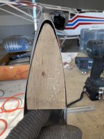
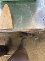
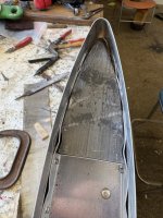
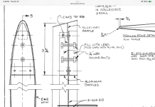
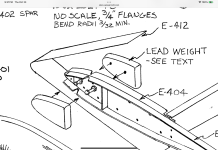
Does anyone have a picture of the placement of the elevator counter weights. According to Van's Tech Support, one cannot purchase this counterweight for the -4. Options are to melt lead and pour it into the space (sounds dangerous) , or purchase the CW for a later model and shave it to fit. I'm especially interested in how to secure it.

TIA,

David
 
Secure with AN “H” bolts into nutplates. The bolt heads are safetied. Standard bolts can be used but should be torque sealed and inspected each preflight. If the bolts loosen then the elevator can jam.
Melting and pouring lead is not especially dangerous and it’s fun! I bet it’s easier than Frankensteining in a different model’s blocks. Just don’t burn yourself…
 
Decided on this method. Sheet of roofing lead, pattern out of plywood. Cut individual pieces and fit/press into the space. Single hole through the elevator and bolt in place.
I don’t think there is enough space on one side to accommodate the needed weight.
Does lead go on both sides and only in the tip?
I’m at layer 5 and not even close to balance. Does the weight go both on the Inside and outside? If only on the outside, that would eliminate the issue of possible jamming.
 

Attachments

  • IMG_1545.jpeg
    IMG_1545.jpeg
    1.4 MB · Views: 32
  • IMG_1546.jpeg
    IMG_1546.jpeg
    3.1 MB · Views: 33
  • IMG_1547.jpeg
    IMG_1547.jpeg
    1.9 MB · Views: 35
I think your method is sound.
-lead inside and outside.
-make your last layer on the outside a primed steel or aluminum plate.
- use 2 bolts fore/aft into nut plates on the outside
-safety wire bolt heads on the inside
Lead is soft and the sheets give up the homogeneous nature of the poured in place method. If the torque slackens over time you want to be able to easily snug things up.
 
Decided on this method. Sheet of roofing lead, pattern out of plywood. Cut individual pieces and fit/press into the space. Single hole through the elevator and bolt in place.
I don’t think there is enough space on one side to accommodate the needed weight.
Does lead go on both sides and only in the tip?
I’m at layer 5 and not even close to balance. Does the weight go both on the Inside and outside? If only on the outside, that would eliminate the issue of possible jamming.
You are making an easy job really difficult, make the dams/baffles as shown, drill holes and install bolts and nuts, seal any gaps with small pieces of aluminum foil and pour the lead, it’s that simple. You will need to pour lead on both sides of the rib to get enough weight. The lead is permanently captured by the bolts.
 

Attachments

  • IMG_6044.png
    IMG_6044.png
    921.4 KB · Views: 27
  • IMG_6043.png
    IMG_6043.png
    703.1 KB · Views: 27
My 6A also has lead weights, I melted lead and poured it into a mould that was roughly the shape of the elevator, but bigger all around. Lead is really easy to trim with a vixxen file.
You may also be able to pour a rectangular block of lead and cut it to the right shape with a bandsaw.
The bolt heads on mine are recessed into the lead, so stacked sheets wouldn't have worked.
The plans call for securing with 1/4" bolts and lock nuts and I also added Loctite thread locker to ensure they don't loosen and jam the elevator.
 
I made molds and poured mine, then drilled them and attached to the counterbalance rib with 2 AN bolts recessed in counterbores. I primed the weights and ribs, then installed them bedded and sealed with Proseal. I did not want them corroding or loosening. I did a ballance pror to final install with paint weight estimate.
 
Back
Top