Good article from Juan.
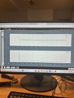
However, I am at a loss as to explain the measurements from Walt *and* why sticking a very large cap in my installation (12KuF) made no difference in the behavior.
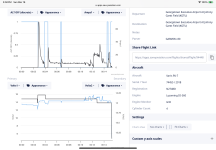
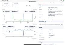
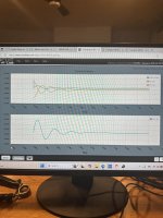
Admittedly, I am lazy and I lack the right tools to measure the ripple voltage and frequency. I did take a run at it with my Fluke 87 Mk.V and came up with .050mVac and 12.90Hz at 1200RPM, 16A with the EarthX battery charged up and online --- but that didn't make much sense either.
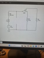
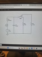
Both the Plane Power and B&C Alternators use a WYE winding with center tap diodes -- 8 diodes total.
I used a different formula for determining frequency -- F = (rpm*poles)/120, maybe that's the error (ref. Juan Grube)...
The capacitance calculation followed from there -- C = I/2f*Vr, Vr is the desired Ripple Voltage, I is the current, F is the frequency in Hz.
For a 1200 RPM scenario, I would need a 47000uF cap to deliver 20A at .5V ripple. 2500 RPM, this drops to 22600uF, same current and ripple.
Big cap on order from Mouser - will be here today; I'll install it and rerun the test and see what happens...
However, I am at a loss as to explain the measurements from Walt *and* why sticking a very large cap in my installation (12KuF) made no difference in the behavior.
Admittedly, I am lazy and I lack the right tools to measure the ripple voltage and frequency. I did take a run at it with my Fluke 87 Mk.V and came up with .050mVac and 12.90Hz at 1200RPM, 16A with the EarthX battery charged up and online --- but that didn't make much sense either.
Both the Plane Power and B&C Alternators use a WYE winding with center tap diodes -- 8 diodes total.
I used a different formula for determining frequency -- F = (rpm*poles)/120, maybe that's the error (ref. Juan Grube)...
The capacitance calculation followed from there -- C = I/2f*Vr, Vr is the desired Ripple Voltage, I is the current, F is the frequency in Hz.
For a 1200 RPM scenario, I would need a 47000uF cap to deliver 20A at .5V ripple. 2500 RPM, this drops to 22600uF, same current and ripple.
Big cap on order from Mouser - will be here today; I'll install it and rerun the test and see what happens...
")