

bt3vex
Active Member
Back Story:
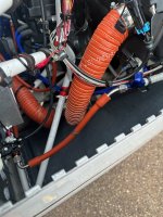
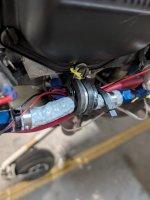
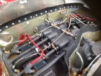
Back in August I was forced to land due to my Fuel Injectors shearing off. (They were the older aluminum fittings) Also according to Rob my fuel hose between the firewall and cylinder #3 did not allow enough room for engine vibration (See Picture). I did have TS flightlines build the fuel hose setup and that seems to be on lots of planes with no issues. Also for that set-up I did not have an Adel clamp in-between the injectors for added support. Regardless of the cause lets fast forward.
I now have the upgraded stainless steel fittings and trying to not repeat the same sequence.
Questions:
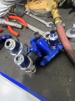
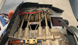
- Yes or No to the Adel clamp? (I feel it makes things too tight because the #1 & #3 or #2 & #4 cylinders move independently of each other, and if I create a clamp point there wont be any room for wiggle. Thoughts or Opinions?
- Length of hose from firewall to #3? (I got a hose that is now 2" longer and creates a slight "S" from the #3 to the firewall. However I feel it now needs support which would potentially defeat the purpose of the longer hose) Thoughts or Opinions?
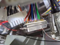
- Keep or lose the system? I have now experienced 3 problems with the system 1. Fuel Injectors failure, 2. faulty soldering on the ECU harness causing the #1 ECU to not work (See Picture), 3. Bad throttle sensor. I am beginning to lose faith in my fuel delivery system and it makes me terrified as it could have killed me at least 2 times now.


 1. Summary of Assumptions
  2. The Calculation Flow
  Final Engineering Verdict