What's new
Van's Air Force

Don't miss anything! Register now for full access to the definitive RV support community.

Cowl Flaps?

MacCool

Well Known Member
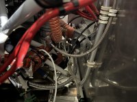
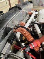
I'm contemplating installing an Anti-Splat cowl flap and I'm looking for installation advice. I have (I believe) a problem with engine compartment temps, which are creating problems under the cowl:
  • hard restarts when hot
  • variable fuel pressures when taxiing
  • premature failure of red cube
  • premature failure of engine driven fuel pump
  • premature failure of boost pump
The red cube and boost pump are both mounted on the firewall. Note that I'm not having issues with CHTs, nor fuel pressure variability while flying.

I haven't actually measured fuel temps or under-cowl temps, although I have a handful of LM34's and a couple of thermocouple gauges, and I hope to have a conversation about that with Pete Howell and/or Alex Peterson at our meeting this Saturday.

My CHT's are fine...always under 400°F even on a hard/hot climb, so this isn't a plenum problem that I'm trying to solve...it's the engine compartment that I'm interested in cooling for the sake of component longevity and to mitigate fuel boiling in the lines.

Anyway, I'm interested in experience with Alan's EZ Cool cowl flap, installation tips, location, etc. YouTube thus far has failed me. Is it reasonable to contemplate installing one in this circumstance?
 
Try leaving your oil filler door open during ground stops. You can easily make a short rod from clothes hanger wire that’ll hold it open.
 
Hard restart when hot is all about technique.
Fuel pressure is not unusual
Put blast tubes on engine driven pump and red cube. Better yet get rid of cube.
Boost pump should be aft of firewall
If your oil temps are ok there is no need for a cowl flap
Starting:
Full throttle
Mixture rich
Just a little bit of prime
Mixture lean
Engage starter
When engine fires mixture rich, slowly
Anything above 80 degrees let the engine accelerate before pulling the throttle back. If you pull the throttle back too rapidly the engine will quit.
I helped a RV10 guy using this technique at Oshkosh. He had repeatedly gotten the engine to fire but it would than quit because he was retarding the throttle too quickly.
Someone mentioned double fire sleeving the line from the injector to the distributor and wrapping it with something like stainless foil tape.
 
Thanks for the input but hard restarting is only a smaller part of the problem and one that is largely solved with insulating tape and exhaust baffling, and a home-made exhaust fan for the oil cooler door. I am also confident in my hot restart procedure. However, the hard restart issue does illustrate my assumption that under-cowl heat is problematic. I'm much more concerned with the fact that in 440 tach hours, this airplane is on its third engine-driven pump, third red cube, and second boost pump.
 
You're in Minnesota and you have heat issues? Unlikely they are worse than what we normally see in TX.
My 2c is go back and replumb the fuel system to stock configuration, boiling fuel is going to be a problem with boost pump FWF.
The only fuel lines FWF should be fire sleeved Teflon, no aluminum or metal lines or gascolators.
Pumps don't take kindly to pumping vapor. I would imagine the engine runs like crap when hot as well.
Keeping the fuel cool is your highest priority.
I also don't understand why folks need cowl flaps or louvers, not required if you've done things correctly, I consider them a band aid in most cases.
Opening the oil door should be more than enough to keep temps down during quick turns.
 
Last edited:
I had the below 1,100 rpm stumble on my newly minted RV-9A (afp-150) after 30 minutes or more of flight time. Stumble would happen on taxi or worse on final if a touch of power was needed. I tried numerous combinations of heat sleave on various fuel related item fwf. What I did 2 months ago that virtually eliminated the stumble…. A 1" blast tube pointed at the mechanical fuel pump, no shroud installed.

Additional note: my RV9A has the new elastomer nose gear assembly. My concern is that all the new "structure" from this assembly inhibits the clean flow of air from behind the engine/accessory case area. The blast tube guides some air to a hot spot.
 

Attachments

  • IMG_2328.jpeg
    IMG_2328.jpeg
    1.6 MB · Views: 102
  • IMG_2327.jpeg
    IMG_2327.jpeg
    1.8 MB · Views: 104
I had the below 1,100 rpm stumble on my newly minted RV-9A (afp-150) after 30 minutes or more of flight time. Stumble would happen on taxi or worse on final if a touch of power was needed. I tried numerous combinations of heat sleave on various fuel related item fwf. What I did 2 months ago that virtually eliminated the stumble…. A 1" blast tube pointed at the mechanical fuel pump, no shroud installed.
Yeah, I just recently replaced the fuel pump. I haven't dissected it yet, but my A&P did suggest that a blast tube might improve longevity. Never had any stumbles or other engine fuel flow symptoms, only fuel pressure fluctuation observable on the EFIS when taxiing.
 
The cowl flaps are great I have 2 of them on my RV-8 and it allows me to make a climb in 95+ degree weather at sea level to an altitude of 15k+ without step climbing while keeping my CHTs at or below 380F.

I would do it again if I had to on another 8 they are a great add on. It’s an immediate difference when you open them up and cool too well at times. So I selectively open or close one at a time to get the results I need for any given ambient temp. Normally I keep them closed for anything below 80 degrees on takeoff.

They also cause drag if you aren’t worried about cooling your cylinders too fast you can use them to slow your speed in a descent.
 
Most people who investigate under cowl temperatures find that accessory temperatures (mags, fuel pump, etc) reach their highest point after shut-down. I would make every effort to create airflow in the space behind the engine during ground stops. The fact that you have good CHT's and the like tells me that dynamic (in-motion) cooling isn't your issue, so cowl flaps are unnecessary. IMO, you need better cooling during the period when your engine compartment is heat soaking after shutdown. Blast tubes won't help there and cowl flaps won't do much unless you can find a way to get the hot air OUT of the cowl - probably by creating a path for convective airflow.
 
An alternative. FWIW. I added blast gates to my louvers. They are only ground adjustable. Blast gates are several layers of fiberglass, slotted for the screws. Nutplates in the louvers inside. Loosen screws. Take a pick and slide the gate open or closed. Tighten the screws. Very little weight gain.
20221028_111943.jpg
 
On my Tailwind with 0 320 with 10-1 pistons, I have a plenum and closed the cowl openings and exit slightly. So my homemade cowl flap is necessary to control the CHT in hot weather. My cowl flap slows the speed 3 knots.
My fuel system is gravity flow so no pumps to deal with.
The OP's engine driven fuel pumps are likely a result of hot fuel caused by the boost pump and the cube. There are shrouds available for the engine pump and with a blast tube that issue should go away.
 
Howard, I agree with Walt. I had a lot of fuel lines wandering around FWF on my initial build (filter - hose to engine pump, hose to servo, hose to firewall, flowmeter, hose to spider). I was ruthless and redid stuff to the bare minimum FWF and it made a big difference. I now have firewall penetration 45 degree fitting, hose to engine pump, hose to flowmeter (suspended and insulated), hose to spider. The filter is below the copilot's legs and is a bit of a pain to service, but still better overall.
 
Howard, I agree with Walt. I had a lot of fuel lines wandering around FWF on my initial build (filter - hose to engine pump, hose to servo, hose to firewall, flowmeter, hose to spider). I was ruthless and redid stuff to the bare minimum FWF and it made a big difference. I now have firewall penetration 45 degree fitting, hose to engine pump, hose to flowmeter (suspended and insulated), hose to spider. The filter is below the copilot's legs and is a bit of a pain to service, but still better overall.
Alex, will you be at KANE on Saturday?
 
I am a fan of experimenting with our experimentals, cowl flaps are certainly one area to experiment. Dan Horton here on VAF has some great advice backed up with a lot of reference material about entry air area vs exit air area IRT cooling efficiencies. Vetterman the exhaust guru also has some neat opinions. Not a lot of folks try to actively vary the entry air area, but being able to modulate the exit air (and hence the entry air) with some kind of adjustable cowl flap has time honored merit for consideration. One aspect many don't immediately consider is the ability to reduce cooling flow when conditions merit. Read that as reducing drag. Strategically placed exit flows in the vicinity of operable cowl flaps also allow you to increase/decrease flows to specific hot boxes such as oil coolers.

Off the shelf cowl flaps are a great start, but they are somewhat restricted in size so that they can fit in an available flat area of the cowling. Consider building your own variable exit(s?) with a precision cut of the cowling itself to form the moving door. That allows you to place the door(s?) in areas where there are complex curves forming. Of course anything cut away will concentrate stress lines so give that some thought.

All that said: Post flight firewall temps are kind of a different cat to skin, not directly addressed by adjustments to normal cooling air flows.
 
You're in Minnesota and you have heat issues? Unlikely they are worse than what we normally see in TX.
My 2c is go back and replumb the fuel system to stock configuration, boiling fuel is going to be a problem with boost pump FWF.
The only fuel lines FWF should be fire sleeved Teflon, no aluminum or metal lines or gascolators.
Pumps don't take kindly to pumping vapor. I would imagine the engine runs like crap when hot as well.
Keeping the fuel cool is your highest priority.
I also don't understand why folks need cowl flaps or louvers, not required if you've done things correctly, I consider them a band aid in most cases.
Opening the oil door should be more than enough to keep temps down during quick turns.
Agree with Walt. Don't know why people stray from standards that have work for many, many, many years. AFP makes a fuel return to help with hot starts. You pull the bypass, pump fuel from tank, through the system up to the flow divider, then back to the tank. Then start you plane normally. Works great for tight cowlings. Red cubes work great when hooked to flex lines and hung in a a fire sleeve pouch. No failures after 20 years......
 
All that said: Post flight firewall temps are kind of a different cat to skin, not directly addressed by adjustments to normal cooling air flows.
Thanks for the input. Firewall temps are my primary concern rather than fuel temperature. Engine cooling is via closed plenum and is apparently quite effective, judging from CHTs. I'm suspicious that flow under the cowl is less so. Fuel temps are a manageable problem and not functionally pressing. I am primarily concerned about the longevity effects on fuel pump, boost pump, and red cube. I have been aware that fuel system routing is less than optimal and I'm not aware of the rationale behind those building decisions, but in looking for temperature solutions, a major fuel system renovation is at the bottom of my preference list.
 
I also don't understand why folks need cowl flaps or louvers, not required if you've done things correctly, I consider them a band aid in most cases.
Heat is heat and these are air-cooled engines. There must be a reason Cessna puts cowl flaps on their aircraft.

-Marc
 
Heat is heat and these are air-cooled engines. There must be a reason Cessna puts cowl flaps on their aircraft.

-Marc
I thought the conversation was about RV's?

So my question is, why am I and many others able to fly the same airplane in the same conditions and have no issues with temps while some folks need louvers/cowl flaps to stay cool? I rarely see cruise temps over 350 at 75% power, typical cruise 65% power puts me around 330 ish even with OAT >80 deg.
(my rv7a is 'stock' per plans build) I can drag my plane around in the Osh pattern at 75K with no concern about temps or sit on the ground waiting to TO without problem. Perhaps I traded a couple knots for this, but I am happy with the outcome.

Just an observation but plenums usually result in higher temps and require faster cruise speeds to keep cool.
The fascination with ignition systems with advanced timing have undoubtedly contributed to the problem.
 
Last edited:
I thought the conversation was about RV's?

So my question is, why am I and many others able to fly the same airplane in the same conditions and have no issues with temps while some folks need louvers/cowl flaps to stay cool? I rarely see cruise temps over 350 at 75% power, typical cruise 65% power puts me around 330 ish even with OAT >80 deg.
(my rv7a is 'stock' per plans build) I can drag my plane around in the Osh pattern at 75K with no concern about temps or sit on the ground waiting to TO without problem. Perhaps I traded a couple knots for this, but I am happy with the outcome.

Just an observation but plenums usually result in higher temps and require faster cruise speeds to keep cool.
The fascination with ignition systems with advanced timing have undoubtedly contributed to the problem.

Among the other possibilities:
  • Angle valve engines like your IO-370 generally have greater cylinder cooling area compared to a parallel valve like the IO-320 asked about
  • New style elastomeric nose gear reduces exit area meaningfully
  • Different operating styles/parameters (ROP vs LOP, ignition timing, etc.)
 
Could you pop a hole in the rear baffle and let some cooler air flow back into the area between the engine and firewall? Otherwise, all you get back there is hot air from the engine if the plenum is sealed tight to the inlets and no other cool air gets through to the back. (just speculating here but it sounds like that's what you're looking for) I'd mount a remote temp sensor behind the engine to see if there's any difference before and after. Easy to plug the hole with a metal plug if it doesn't work (or make an adjustable blocker with a piece of metal and a bolt to rotate it open and closed).
 
The issue is not engine temperatures. Two of the issues are fuel pumps. Cowl flap will not cure the short life of the fuel pumps. Given the engine temperatures a cowl flap would be a waste of time
 
Could you pop a hole in the rear baffle and let some cooler air flow back into the area between the engine and firewall? Otherwise, all you get back there is hot air from the engine if the plenum is sealed tight to the inlets and no other cool air gets through to the back. (just speculating here but it sounds like that's what you're looking for) I'd mount a remote temp sensor behind the engine to see if there's any difference before and after. Easy to plug the hole with a metal plug if it doesn't work (or make an adjustable blocker with a piece of metal and a bolt to rotate it open and closed).
Yes thanks. My AP and I are contemplating a blast tube for the fuel pump. I'm kind of waiting until I get the chance to cobble up an actual temp measuring device and quantify the under-cowl temps.
 
The issue is not engine temperatures. Two of the issues are fuel pumps. Cowl flap will not cure the short life of the fuel pumps. Given the engine temperatures a cowl flap would be a waste of time
A cowl flap won't mitigate temps under the cowl and along the firewall? I'm trying to think why not.
 
Heat is heat and these are air-cooled engines. There must be a reason Cessna puts cowl flaps on their aircraft.

-Marc
Because most Cessna's cannot pump 2500 cfm through their cowling due to the forward airspeed (or lack there of). Also, Cessna is in the business of making airplanes and you take a look at most Continentals, you'll see why. The baffling sucks or there almost is none. They don't want to spend the manpower or money to build a highly complex baffling system like we have on our RV's. Their cowlings are also not much better when it comes to aerodynamics. It's fit and form and about the all mighty dollar to build an airplane and work on it. Half their cowl flaps end up in a field or forest some where because they fall off a lot. Our time is "free" and we put a lot more effort and efficiencies in our engine/baffling systems to make sure they cool well and work in all regimes of flight.
 
Yes thanks. My AP and I are contemplating a blast tube for the fuel pump. I'm kind of waiting until I get the chance to cobble up an actual temp measuring device and quantify the under-cowl temps.
I used a piece of plastic (not split) 1/2" conduit and popped it in a hole in the rear baffle and attached it so it blows directly on my mechanical fuel pump. I have an O-320, and don't have hot start issues, but I figured it couldn't hurt. I also have a tube that directs cool air directly on the back of my alternator.

A wireless meat thermometer (found on amazon) that connects to your phone might do the trick.
 
The location of the engine driven pump makes it unlikely that the cowl flap will move any additional airflow over the fuel pump. The airflow with the plenum is going out the bottom of the cylinders and it is highly unlikely there will be any increased flow over the fuel pump. Normally cowl flaps are only used for takeoff and climb. The fuel pump needs additional full time airflow. Pump doesn't need much flow if it is done properly.
 
The location of the engine driven pump makes it unlikely that the cowl flap will move any additional airflow over the fuel pump. The airflow with the plenum is going out the bottom of the cylinders and it is highly unlikely there will be any increased flow over the fuel pump. Normally cowl flaps are only used for takeoff and climb. The fuel pump needs additional full time airflow. Pump doesn't need much flow if it is done properly.
Good point, thanks.
 
in 440 tach hours, this airplane is on its third engine-driven pump, third red cube, and second boost pump.
Where is your boost pump located? What's different about your installation than the thousands of other side by side airplanes which don't fail these components on a routine basis?
 
His CHTs are fine. How does ignition timing cause failures of the red cube, fuel pump or any other accessory?
I was speaking in general terms, higher CHT's (I don't believe the OP ever gave an actual number) will make everything hotter, oil, eng case, mags, fuel pump etc.. Plus, he it shows he's located in MN for goodness's sake, I wonder how he would do where I live where daytime temps are currently averaging 90-100 in the shade (generally the pilot is the one that can't handle the heat, not the aircraft).

He's looking for a band aid solution to his problem as he's already stated he doesn't want to dig too deep.
IMO he's living on the edge, that many failures is trying to tell you something and it should be taken very seriously.

A friend once told me think about your decisions carefully, and how the NTSB report will read if you make the wrong one!
 
Last edited:
I was speaking in general terms, higher CHT's (I don't believe the OP ever gave an actual number) will make everything hotter, oil, eng case, mags, fuel pump etc.. Plus, he it shows he's located in MN for goodness's sake, I wonder how he would do where I live where daytime temps are currently averaging 90-100 in the shade (generally the pilot is the one that can't handle the heat, not the aircraft).

He's looking for a band aid solution to his problem as he's already stated he doesn't want to dig too deep.
IMO he's living on the edge, that many failures is trying to tell you something and it should be taken very seriously.

A friend once told me think about your decisions carefully, and how the NTSB report will read if you make the wrong one!
From the rear baffle/plenum to the firewall the higher up on that area the less airflow the area is going to get. Mags. engine driven fuel pump etc are all subject to heat damage. A blast tube 3/4 to 1" diameter will reduce the heat significantly. In addition some of the spam cans use a shroud around the engine driven pump which provides additional cooling.
 
He's looking for a band aid solution to his problem as he's already stated he doesn't want to dig too deep.
IMO he's living on the edge, that many failures is trying to tell you something and it should be taken very seriously.
Agree that there is something else going on here. Would be nice to know what the nature of the failures are. I have a hard time believing this airplane is so much hotter than everyone else that these normally robust accessories are failing due to heat. It's just not that hot behind the baffles.
 
I was speaking in general terms, higher CHT's (I don't believe the OP ever gave an actual number) will make everything hotter, oil, eng case, mags, fuel pump etc.. Plus, he it shows he's located in MN for goodness's sake, I wonder how he would do where I live where daytime temps are currently averaging 90-100 in the shade (generally the pilot is the one that can't handle the heat, not the aircraft).

He's looking for a band aid solution to his problem as he's already stated he doesn't want to dig too deep.
IMO he's living on the edge, that many failures is trying to tell you something and it should be taken very seriously.

A friend once told me think about your decisions carefully, and how the NTSB report will read if you make the wrong one!
I have a plenum. CHT's are fine. Typically 350° in cruise at 75% power, never have seen 400° on any cylinder at any power setting at any ambient temp.
 
Let's see some photos of the engine compartment, in particular the areas around the failing accessories.

I have a decent library of engine compartment temperatures, my own and a dozen others. Assuming low leakage (Mac said he has a plenum and good CHTs), a 320 installation in a -9 will probably show inflight exit air temperatures in the 150 to 170F range this time of year. The 390 installation in my -8 has better heat transfer than any 320 (a property of the angle valve heads) and will record exit air temperatures in the 170 to 190F range. First engine driven pump lasted 10 years. Still running the original (circa 2008) red cube and AFP boost pump. No blast tubes, no bandaids.

Point is, air temperature is unlikely to fail accessories (not really hot enough), nor will it be significantly different from 10,000 other installations.

If the failures are temperature related, the likely culprit is radiant heating. I've seen some truly awful examples, and recorded some rather large numbers.

We will get Mac the temp recording rig on Saturday and grab some data.
 
Let's see some photos of the engine compartment, in particular the areas around the failing accessories.

I have a decent library of engine compartment temperatures, my own and a dozen others. Assuming low leakage (Mac said he has a plenum and good CHTs), a 320 installation in a -9 will probably show inflight exit air temperatures in the 150 to 170F range this time of year. The 390 installation in my -8 has better heat transfer than any 320 (a property of the angle valve heads) and will record exit air temperatures in the 170 to 190F range. First engine driven pump lasted 10 years. Still running the original (circa 2008) red cube and AFP boost pump. No blast tubes, no bandaids.

Point is, air temperature is unlikely to fail accessories (not really hot enough), nor will it be significantly different from 10,000 other installations.

If the failures are temperature related, the likely culprit is radiant heating. I've seen some truly awful examples, and recorded some rather large numbers.
Good to have some numbers, Dan. Thanks for your input. I hope to have actual temp data soon. Here are some engine compartment photos. They're from a couple of years ago...don't show the current fuel line insulation and exhaust baffling.

IMG_1079.jpegIMG_8463.jpegIMG_8462.jpeg
 
We will get Mac the temp recording rig on Saturday and grab some data.

Excellent. Be sure to use radiant shields where necessary if the goal is air temperature.

Good to have some numbers, Dan. Thanks for your input. I hope to have actual temp data soon. Here are some engine compartment photos.

As shown, that's a fuel heater setup for sure.

Re the boost pump, red cube, and engine driven pump, what is the nature of the failures? Do any autopsies to find failed parts, or were they simply replaced due to a perception of poor performance?
 
Good to have some numbers, Dan. Thanks for your input. I hope to have actual temp data soon. Here are some engine compartment photos. They're from a couple of years ago...don't show the current fuel line insulation and exhaust baffling.

View attachment 66347View attachment 66348View attachment 66349
Here is a leap, FWIW. I'm only talking the flow meter and boost pump.

First off; in a scan of the thread I don't know if the boost pump proper failed or the motor.

Looking at your installation, you're not doing your components any favors from a stress standpoint. Short/straight for fluid lines is rarely a good combo when temperature changes are involved. As a bare minimum, steam loop the tube between the two aforementioned components. Easy enough, get rid of the elbow and reconfigure the tube. This will greatly diminish the stresses xferred from the tubing to the components. I'd also consider insulating this line and potentially others. This, or get a fire-sleeved flexline from Tom/TSFlightlines.

Previous failure modes would need to be determined to predict any potential impact. Not saying this is 100% of your problem but I'll reiterate, you're not doing these two components any favors in the current configuration. My $0.02
 
Excellent. Be sure to use radiant shields where necessary if the goal is air temperature.

As shown, that's a fuel heater setup for sure.

Re the boost pump, red cube, and engine driven pump, what is the nature of the failures? Do any autopsies to find failed parts, or were they simply replaced due to a perception of poor performance?
Don't know about the first fuel pump failure, replaced with a Tempest. That pump failed about 200 hours later...wasn't pumping, airplane was AOG (happened on the ferry flight home after purchase). Dissection showed a hole/tear in the diaphragm..replaced with a Tempest. Most recent failure of that pump was pressure variability on the fuel pressure gauge and engine stumbling only while taxiing on hot days. That stumbling wasn't really affected by hitting the boost pump although it did raise the fuel pressure as expected. I haven't taken that pump apart yet...not completely sure it was a failure but the gauge variability did resolve with the new pump. I'll take it apart today. The red cube...it just started intermittently not showing fuel flow. Boost pump failure a couple of years ago...it was working fine, but AP found some fuel staining at CI that year, indicating a small leak. I didn't' take it apart...returned for core.

Brief video of what I saw for fuel pressure readings with this most recent fuel pump issue. With and without boost pump.

 
I have two on my 10 Cowling. The install is pretty straight forward and they work nicely. You will have to run the wires to the servo, or servo's and have to remember to unhook the those before dropping the cowl. The other benefit for my install, is that after climbing up and things cool off, you can close them and reduce drag.
 

Attachments

  • 100_0009.JPG
    100_0009.JPG
    2.5 MB · Views: 31
Looking at your installation, you're not doing your components any favors from a stress standpoint.
Completely agree and that jumped out at me immediately. I’m a fan of hard lines wherever possible, but there are design considerations that go with their installation. Perfectly straight tubes like that one are rarely acceptable unless the fittings are installed in a very stiff, monolithic component, and the component, fittings and line itself has the same coefficient of thermal expansion. You certainly do not have that condition here. That floppy, drumming stainless firewall is going to drive a lot of stress into that single tube. And because that tube is essentially straight, it acts as a structural member that is resisting movement. Problem is, the stresses will resolve into the flare, and that’s the weakest part of the tube. And that tube looks like aluminum.

Early in my career in aerospace an experienced Lockheed design engineer gave me a nugget that has stuck with me forever: generally, any hard line installation should have a minimum total of 90 degrees of bend along its length to effectively cripple the tube and remove its structural properties. Two 45’s in a “Z” works as does three 30’s…. As long as you have at least 90 degrees in the run. And while you are at it, make that tube out of stainless. The fatigue and fire resistance of stainless are far superior to aluminum. Same tools are required to fabricate, so why not?

All this is assuming you are going to keep these components in their current position, of course. It’s been my experience that the Weldon pump should be mounted vertically, with the fuel chamber at the bottom. Better for the vanes, and reduces the chances of fuel flooding the motor in case of an internal leak. Not sure if this is a “rule”, “best practice”, or OWT, but that‘s what I have seen in the field.
 
Last edited:
Don't know about the first fuel pump failure, replaced with a Tempest. That pump failed about 200 hours later...wasn't pumping, airplane was AOG (happened on the ferry flight home after purchase). Dissection showed a hole/tear in the diaphragm..replaced with a Tempest. Most recent failure of that pump was pressure variability on the fuel pressure gauge and engine stumbling only while taxiing on hot days. That stumbling wasn't really affected by hitting the boost pump although it did raise the fuel pressure as expected. I haven't taken that pump apart yet...not completely sure it was a failure but the gauge variability did resolve with the new pump. I'll take it apart today. The red cube...it just started intermittently not showing fuel flow. Boost pump failure a couple of years ago...it was working fine, but AP found some fuel staining at CI that year, indicating a small leak. I didn't' take it apart...returned for core.

Brief video of what I saw for fuel pressure readings with this most recent fuel pump issue. With and without boost pump.

Good data point(s) but it gives you something else to consider.

Assuming:
- the (noticeable) stumbling goes away at higher power settings with boost pumps on
- you are running Avgas

These symptoms align nicely with a fuel system leak (air ingress) upstream of the boost pump. Check for any staining but know that there may not be any. Not unheard of to have a "one way" leak. It's usually a pretty easy/cheap check. We tend to overcomplicate thing and overlook the simple. Keep us informed.
 
Last edited:
Don't know about the first fuel pump failure, replaced with a Tempest. That pump failed about 200 hours later...wasn't pumping, airplane was AOG (happened on the ferry flight home after purchase). Dissection showed a hole/tear in the diaphragm..replaced with a Tempest. Most recent failure of that pump was pressure variability on the fuel pressure gauge and engine stumbling only while taxiing on hot days. That stumbling wasn't really affected by hitting the boost pump although it did raise the fuel pressure as expected. I haven't taken that pump apart yet...not completely sure it was a failure but the gauge variability did resolve with the new pump. I'll take it apart today. The red cube...it just started intermittently not showing fuel flow. Boost pump failure a couple of years ago...it was working fine, but AP found some fuel staining at CI that year, indicating a small leak. I didn't' take it apart...returned for core.

Mac, before I spent time and money on cowl flaps, I'd revise the fuel system.

The boost pump should be behind the firewall, where it is cool. Elbows should be minimized in the plumbing between the tank selector and the boost pump. Bring the fuel through the firewall with a SS bulkhead fitting, then run a short, insulated teflon hose directly to the engine driven pump. The red cube should be downstream of the engine driven pump. It's a moderate flow restriction. And do you see a fuel flow change when you switch the boost pump to ON?
 
These symptoms align nicely with a fuel system leak (air ingress) upstream of the boost pump. Check for any staining but know that there may not be any. Not unheard of to have a "one way" leak. It's usually a pretty easy/cheap check.

How would you check for that if there is no visible stain?
 
How would you check for that if there is no visible stain?
Turn the selector to “off”, disconnect the fuel hose at the engine driven pump and attach a Mity Vac. Draw a vacuum and look for the gauge to hold a vacuum. Alternately, go all the way to the tank(s) and plug the line at the tank fitting, and attach the Mity Vac to the line that enters the servo/carb.
 
With the exception of the stainless lines on the IO Lycomings, there is no way I would have hard lines forward of the firewall. While some of the exact failure modes are not known there have been a number of fatal accidents due to fuel plumbing. Harmon Rocket fatal to pilot, passenger in back seat minor injuries. The RV8 where the pilot jumped out without a chute. The AOPA guy in the Cessna Cardinal. Video of a Beech Duke trailing fire and then exploding.
 
Turn the selector to “off”, disconnect the fuel hose at the engine driven pump and attach a Mity Vac. Draw a vacuum and look for the gauge to hold a vacuum. Alternately, go all the way to the tank(s) and plug the line at the tank fitting, and attach the Mity Vac to the line that enters the servo/carb.
Good input. What if you use that method and the results show you have a leak. It’s small, so maybe the offending connection isn’t obvious. How do you track down the specific connection that's leaking? For what it is worth, I count 8 connections between the tank and mechanical pump.
 
Good input. What if you use that method and the results show you have a leak. It’s small, so maybe the offending connection isn’t obvious. How do you track down the specific connection that's leaking? For what it is worth, I count 8 connections between the tank and mechanical pump.
You can sometimes hear the leak. Sometimes you can apply soapy water (Snoop) and observe the leak as its drawn in, and sometimes you can break torque, inspect, and retorque.

The vacuum test is often one of the first test procedures we do on new aircraft rolling down the Mfg line. It's basic stuff, but if it works on 6th gen combat aircraft....
 
Back
Top