Van's Air Force

The definitive Van's Aircraft support community! Buying, building or flying an RV? Join our exclusive family of mentors and enthusiasts!

Cowl Flap wiring

SeanB

Well Known Member
Friend
Hello,

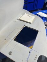
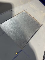
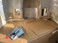
I'm considering installation of two Anti Splat Aero Cowl Flaps. For those of you that have installed two of them, did you also use two switches or merge into one? One fuse or separate them with two? Did you have to dig out the honeycomb material in the bottom corners of the lower cowl then do fiberglass layups?

Thanks!
 
I installed two cowl flaps on my -7 to reduce CHTs on climb out. Works.

Used one switch with a flashing idiot light to remind my dumb ass to close it at cruise. Used in-line fuse.
Wired both around the lower cowl to the upper rear right side with connector to firewall wiring.

Didnt dig into the cowl honeycomb corners. The flap plate is flat but the cowl bottom is slightly curved in both axis.
I set the plate corners flush with cowl then filled in middle of plate to match cowl curves. Was up to 1/8" to 3/16" thick at spots.
(also put lightening holes in the plate since I was glassing over the middle.

Be advised, operation-maintenance can be a bugger.
After 300 hours, the wiring across bottom of the cowl can get oily, and one of the actuators has gone out (assume it is from oil intrusion).
 
I used a single switch for two flaps as well. 100 hours and no issues so far. I only need them when OAT is over 95F...which has been common this year.
 
Only one flap and switch for me but if I were to install a second one I would just have one switch. I also have an indicator light. Be aware that the actuator wires are very small and fragile. After a while they broke right at the exit of the actuator and I was unable to repair it. On the second actuator I ran the wire back over the actuator body and used heat shrink to secure it so there would be no flexing or strain on the wire. FWIW
 
Thanks, everyone! I may investigate replacing those wires if the actuator is easy enough to open.
 
Just installed my second one. I have had 2 flights since the second was installed on the right side, one switch. Both flights in August Texas Heat, CHT's running 15 degrees cooler right after runup and takeoff . Had to pinch myself after runup and climb out not seeing CHT's running 420.
 
I installed two in my -7 lower cowl a number of years back. Easy to mount. Just used four screws with nut plates.

Works quite well at cooling on hot take-off days. I can notice a difference in speed and trim when I close them when I start cruise flight. I used one switch, in line fuse.

I also open them when doing a refueling stop. Put the tail into the breeze and help cool down fuel injection lines to make 'hot start' easier.

Used silver metal tape to cover and attach the wires along inner surface of cowl and have a couple crimp-spade terminals near the oil door and a printed label to remind me to disconnect before pulling lower cowl.

I did have an early actuator fail so now I keep a spare on the shelf. Unused for quite some time, but it is there due to a corollary of Murphy's Law. Just like the spare flap motor, spark plugs, Airstop tube, segmented alternator belt etc.

Am happy with them and other A.S. products. Just bought the gust stop.
 
Hi Everyone! I finally decided to begin making the cuts to install two ASA Cowl Flaps on my -7. I'm still a little confused on how to handle the exposed honeycomb edges of the cut. Oversize the cut a bit, the fill the voids of the honeycomb edge with a micro mixture, then overlap with cloth? My hope is to use nutplates on the metal frame of the Cowl Flaps, so they are removable. I also have some concern of countersunk attach screws from the outside compressing the honeycomb material, or even punching thru with time. Yes, I will also need to "float" the flap to handle the curvature of the cowl. Any ideas or guidance/pics appreciated! Thanks!
 

Attachments

  • IMG_1932.jpeg
    IMG_1932.jpeg
    1.5 MB · Views: 53
  • IMG_1934.jpeg
    IMG_1934.jpeg
    1.9 MB · Views: 51
Hi Everyone! I finally decided to begin making the cuts to install two ASA Cowl Flaps on my -7. I'm still a little confused on how to handle the exposed honeycomb edges of the cut. Oversize the cut a bit, the fill the voids of the honeycomb edge with a micro mixture, then overlap with cloth? My hope is to use nutplates on the metal frame of the Cowl Flaps, so they are removable. I also have some concern of countersunk attach screws from the outside compressing the honeycomb material, or even punching thru with time. Yes, I will also need to "float" the flap to handle the curvature of the cowl. Any ideas or guidance/pics appreciated! Thanks!
You’ll want to spoil the honeycomb approximately 1/4-1/2” back from the cut line. Then pack with a flox/epoxy mixture. You shouldn’t need a layer of glass.
 
Hi Everyone! I finally decided to begin making the cuts to install two ASA Cowl Flaps on my -7. I'm still a little confused on how to handle the exposed honeycomb edges of the cut. Oversize the cut a bit, the fill the voids of the honeycomb edge with a micro mixture, then overlap with cloth? My hope is to use nutplates on the metal frame of the Cowl Flaps, so they are removable. I also have some concern of countersunk attach screws from the outside compressing the honeycomb material, or even punching thru with time. Yes, I will also need to "float" the flap to handle the curvature of the cowl. Any ideas or guidance/pics appreciated! Thanks!
Drill and countersink into the cowl & honeycomb. Maybe oversize a little. Inject a thin mix of resin-flux & swirl around the hole and countersink to soak in and reinforce. Then re-drill and countersink to fit. On my double flap install, this has avoided the screws sinking into the honeycomb.
 
Rob and Bruce....thanks for your replies and excellent ideas.

Rob, when you describe "spoiling" the honeycomb, I take that as digging out the honeycomb material for approximately 1/4-1/2", while leaving the inner and outer fiberglass shell intact. Digging out a void, then packing with epoxy/flox mix. Am I understanding correctly?

Bruce, similar idea it seems with your approach. I'm using a slightly deeper countersink to expose some of the voids in the honeycomb, then injecting epoxy/flox into the exposed pockets, then countersink again once dry to fit. Correct?

Thanks again, Gentlemen!
 
We used to create a recess at the edge for adhesive. I used to have a bolt that I hacked up with a cutoff wheel to tear out the material when chucked up in a drill.

Tape up the edges and butter the edge with epoxy. The last thing you need is oil and grime getting between the inner and outer layers.
 
Rob and Bruce....thanks for your replies and excellent ideas.

Rob, when you describe "spoiling" the honeycomb, I take that as digging out the honeycomb material for approximately 1/4-1/2", while leaving the inner and outer fiberglass shell intact. Digging out a void, then packing with epoxy/flox mix. Am I understanding correctly?

Bruce, similar idea it seems with your approach. I'm using a slightly deeper countersink to expose some of the voids in the honeycomb, then injecting epoxy/flox into the exposed pockets, then countersink again once dry to fit. Correct?

Thanks again, Gentlemen!
Thats correct. We have some core materials at work that will absorb water and degrade, making the spoiling process time sensitive. A piece of piano hinge wire bent to 90 degrees and chucked into a dremmel makes a good spoiling tool.
 
Great idea on the bent piano hinge, Rob. BTW...I just ran across pics of your plane.....so cool!
 
I remember reading that heat shortens the actuator life?? I wrapped the actuator with fiberfrax then aluminium tape and finally a couple of cable ties to keep it all in place.
Fin 9A
 
Chamfer the honeycomb back over about 1", leave a 1/2" land to attach to. fill the exposed cells with micro balloons - can be quite a stiff mix. Cover with 2 or 3 layers of glass, more close to the hole if the cloth is thin to give enough depth to counter sink. Overlap 0.5 to 1" away from the hole. None of the dimensions are at all critical
 
This example is a single ply of carbon on each side of honeycomb, so load transfer to the face plies is critical. It was a bagged we layup, so there was going to cured epoxy in some cells, meaning the classic "bent wire through a hole" trick probably wouldn't work anyway. So, a hole saw to remove a face ply from one side, dig out the core, fill with flox/epoxy, and cap it with a new face ply or two while wet. The advantage to this approach is uniformity, mostly no trapped air. The hard point is truly hard.

IMG_20200815_152337152.jpg
IMG_20200815_153910018.jpg
IMG_20200815_154403899.jpg
IMG_20200816_091451477.jpg

IMG_20210123_093846037.jpg

When you need to fill an edge, rip out the core to a depth of about 1/4". It's easy if you spend a few minutes making an edge ripper tool. Bend a old screwdriver, grind the end to a flat blade, then grind the width to match the thickness of the core you want to remove. Tack weld a little crossbar on it to set the cutting depth.

Ripper.jpg

Fill with flox/epoxy, or flox/micro/epoxy, or micro/epoxy. Choice depends on balancing sanding ease with impact toughness.

PB180002.JPG
 
Wow! More great replies/ideas! Dan, I really like the idea for the ripper tool. Guessing I could also adapt a bent pick, too. I tried the bent wire in a drill approach last night. I had some success, but I didn't have great skill executing, so switched to my Dremel with a thin cut off wheel to hollow the edge. I was able to control that much better. It was nerve wracking trying to keep it in the honeycomb without drifting into the glass shell. A manual approach seems much better due to the thin edge. Thanks again to everyone for the excellent ideas and pics!
 
Retro-fitting dual, single switch (undecided, got some DPDT ON-OFF-ON, same but spring loaded to OFF, and the original 3 lbs ON/ON switch. Micro balloons on the opening flanges, 2 bolts in the middle flanger for each flap with Tinnerman washers (microed the holes and area). Cowl contour ok. I'll try to recall to post some pics once done...
 

Attachments

  • IMG_5809.jpg
    IMG_5809.jpg
    852.4 KB · Views: 26
Back
Top