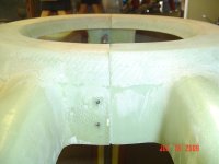
The question is: when in the cowl fitting sequence to cut off the rebate along the side edges of the lower cowl where the upper cowl overlaps and where the piano hinge attaches. (It is unclear why the rebate is molded in, unless it is to help during fitting.)
There isn't any mention of the rebate in the construction manual, but the drawing shows the shaded area that needs to be trimmed off.

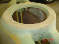
I have so far installed the top cowl and cleco'd on the boot cowl piano hinge. The bottom cowl is trimmed and fitted on temporarily with straps. The next step would be to either: 1) attach the vertical piano hinges at the sides or 2) trim off the horizontal rebate flange first and only then attach the vertical hinges.


Thanks if you know the answer!
There isn't any mention of the rebate in the construction manual, but the drawing shows the shaded area that needs to be trimmed off.
I have so far installed the top cowl and cleco'd on the boot cowl piano hinge. The bottom cowl is trimmed and fitted on temporarily with straps. The next step would be to either: 1) attach the vertical piano hinges at the sides or 2) trim off the horizontal rebate flange first and only then attach the vertical hinges.
Thanks if you know the answer!
 But hey, I did have the green/honeycomb core cowl like yours!