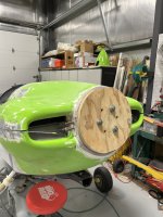
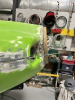
I am soon to get my engine home, which means I can start work on the cowl.
However the -14 plans show the prop installed in chapter 44 before the cowl in chapter 45.
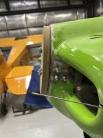
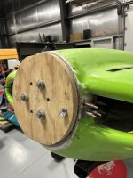
Can I use some spacers for this purpose like I have seen mentioned in the -7 threads? (I sadly don’t have the cash for a prop at the moment given the massive outlay the engine has represented).
Has anyone used the Hartzell 3D printed hub models for this purpose instead of spacers? Made by the very knowledgeable @TParker ?
However the -14 plans show the prop installed in chapter 44 before the cowl in chapter 45.
Can I use some spacers for this purpose like I have seen mentioned in the -7 threads? (I sadly don’t have the cash for a prop at the moment given the massive outlay the engine has represented).
Has anyone used the Hartzell 3D printed hub models for this purpose instead of spacers? Made by the very knowledgeable @TParker ?
Hartzell Hub and Blade Proxies
In an effort to make things easier where I can, I've developed a set of 3D printed files that can be used to make proxies for Hartzell hubs and blades. I think this would allow the actual bulkhead to be mocked up to the cowling and also make spinner cutouts easier. I've got hubs for the most...
vansairforce.net