Van's Air Force

The definitive Van's Aircraft support community! Buying, building or flying an RV? Join our exclusive family of mentors and enthusiasts!

Comment on my RV10 Antenna Plan

RV6-KPTW

Well Known Member
Friend
Hi all,

I see a lot of different ways to mount antenna on the RV10. I have seen enough RV10s that my selected approach seems reasonable.

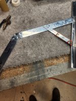
See the attached drawing snip for proposed locations.

Comm Antennas – I have questions on this location and approach.
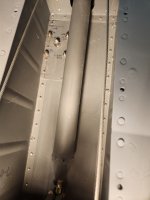
  • Propose mounting just behind the trailing edge of the rear wing spar
  • This location is under the rear passenger seat pan. I was not going to add an access panel. I will add a service loop(ish), doubler, and nutplates before final riveting the seat pan.
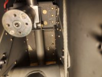
  • I think that the 2nd bay in board will result in a comm antenna separation of about 36” – see photo
  • Has anyone had comm issues with the antennas in this location? I had an RV6 with comm antennas between the landing gear where I had to turn 90 degrees to talk to ground or tower. Never any problems in the air (that I knew).
Transponder antenna
  • Mounted under copilot or pilot front seat floor cover aft of control system hardware.
ADSB antenna
  • Mounted aft of the baggage bulkhead – need to work around all the things located in that area so no specific detail location yet.
NAV antenna
  • Archer in wingtip
Thanks,

Dennis
IMG_5551.jpegIMG_5555.jpeg
 
I suggest mounting the comm antennas in the tunnel area. One as far forward and to the left of centerline as possible, one as far aft and right of the centerline as possible. This eliminates interference with the elevator push tube and avoids burying the antennas under the rear seat, making maintenance an issue.

I mount the ADS-b receiver and antenna aft of the baggage compartment bulkhead. I made a tray out of 0.040” aluminum in a flat U shape. The tray “feet” get prosealed to the inside of the bottom of the fuselage. The antennas is mounted a few inches from this. The receiver is connected to the SkyView with a single, four #22 conductor shielded cable (power, ground, serial and serial ground).

If you want, you can modify the wingtip VOR/LOC/GS antenna to take advantage of the wider wingtip. This does require use of an antenna analyzer. I just made four of these out of the RV-10 aluminum cutoff bundle.
 

Attachments

  • IMG_2788.jpeg
    IMG_2788.jpeg
    1.4 MB · Views: 33
I suggest mounting the comm antennas in the tunnel area. One as far forward and to the left of centerline as possible, one as far aft and right of the centerline as possible. This eliminates interference with the elevator push tube and avoids burying the antennas under the rear seat, making maintenance an issue.
I did not see this center line comm antenna variation but am intrigued. One can go pretty far forward and aft in the tunnel to clear interference from the landing gear. Do you have photos or layout drawings? I’ll wing it otherwise.

Thanks
 
I did not see this center line comm antenna variation but am intrigued. One can go pretty far forward and aft in the tunnel to clear interference from the landing gear. Do you have photos or layout drawings? I’ll wing it otherwise.

Thanks
Sure. DM me your email and I‘ll send later this weekend.

Carl
 
I didn’t see an ELT antenna.
Edit. Archer works fine, skip the eye-poking cat whiskers. Keep it aft of wires to lights. Carl has a clever mounting solution (aluminum angle attached to the end rib) which makes taking the tip on or off easier.
 
I did not see this center line comm antenna variation but am intrigued. One can go pretty far forward and aft in the tunnel to clear interference from the landing gear. Do you have photos or layout drawings? I’ll wing it otherwise.

Thanks
As I mentioned, mounting the comm antennas in the tunnel eases maintenance and access pain. One is far forward and to the left of centerline as possible, one as far aft and right of the centerline as possible. This eliminates interference with the elevator push tube and avoids burying the antennas under the rear seats, making maintenance an issue.

The first photo is the forward antenna (and doubler plate). Note the two inboard antenna mounting screws and associated nuts are hidden in the photo by the elevator push tube. The second photo is the aft antenna and doubler plate. Note the aft doubler plate is joggled on one side to go over the rib lip. On that lip it shares the rivets with the rib.

Coax runs to the panel using the tunnel. Adel clamps hold the coax in place.

Carl
 

Attachments

  • IMG_2810.jpeg
    IMG_2810.jpeg
    844.5 KB · Views: 34
  • IMG_2811.jpeg
    IMG_2811.jpeg
    1 MB · Views: 34
Back
Top