

Hi everyone.
In the plans on Page 7-2, they say:
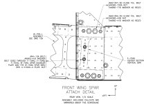
"Attach the two K1000-4 center section attach platenuts to the forward side of the spar. Countersink the W-706C doubler plate to allow the flush heads of the rivets to rest on the aft side of spar. This allows the doubler plate to fit flush against the F-804G-1 vertical bars (DWG 11A or 73)."
The problem is, I don't have a drawing 11A, and my drawing 73 is all about the tail wheel, nothing to do with the wings. And I see nothing documented about what W-706C or F-804G-1 are. None of the references they give for the procedure seem relevant at all.
I *think* I know the two places K1000-4 platenuts they are referring to are to be attached to the spar (If I'm right, they are on the web just a few inches from the root end of the wing spars, and I presume that W-706C might be the doubler plate already riveted in place at the factory to form part of the spar assembly, though I can't find any diagram to confirm this). But since installation of the nutplates involves countersinking into the spar, which is a rather big deal to make sure is done right the first time, I'm hoping if anyone can give some clarification on this.
I'm building an RV-8 after having completed an RV-10, and I now realize how much better the plans became with later models of RVs. I find I'm having to make a lot of assumptions in the RV-8 plans that would be so quickly resolved with a simple diagram every now and then.
Thanks for the help!
In the plans on Page 7-2, they say:
"Attach the two K1000-4 center section attach platenuts to the forward side of the spar. Countersink the W-706C doubler plate to allow the flush heads of the rivets to rest on the aft side of spar. This allows the doubler plate to fit flush against the F-804G-1 vertical bars (DWG 11A or 73)."
The problem is, I don't have a drawing 11A, and my drawing 73 is all about the tail wheel, nothing to do with the wings. And I see nothing documented about what W-706C or F-804G-1 are. None of the references they give for the procedure seem relevant at all.
I *think* I know the two places K1000-4 platenuts they are referring to are to be attached to the spar (If I'm right, they are on the web just a few inches from the root end of the wing spars, and I presume that W-706C might be the doubler plate already riveted in place at the factory to form part of the spar assembly, though I can't find any diagram to confirm this). But since installation of the nutplates involves countersinking into the spar, which is a rather big deal to make sure is done right the first time, I'm hoping if anyone can give some clarification on this.
I'm building an RV-8 after having completed an RV-10, and I now realize how much better the plans became with later models of RVs. I find I'm having to make a lot of assumptions in the RV-8 plans that would be so quickly resolved with a simple diagram every now and then.
Thanks for the help!