Greg Arehart
Well Known Member
Here's what I've been doing when I can't do any test flying....
A couple weeks ago I posted a request here regarding build-your-own remote cellphone-operated switch to turn on my engine heaters remotely. I finished putting this together tonight. Total cost about $50 as follows:
$11 - 4 x 6 x 6 plastic junction box from Home Depot (includes a sealable waterproof lid!)
$18 - Apogee kit (http://www.apogeekits.com/remote_control_via_cell_phone.htm) including shipping
$10 - cheap walmart cellphone, comes with 10 minutes (good for 30 days)
$20 - optional additional minutes, good for 90 days

This photo shows the wiring inlet - standard electrical fixture (I got a waterproof one, but unless this is outside, waterproof is probably not necessary)

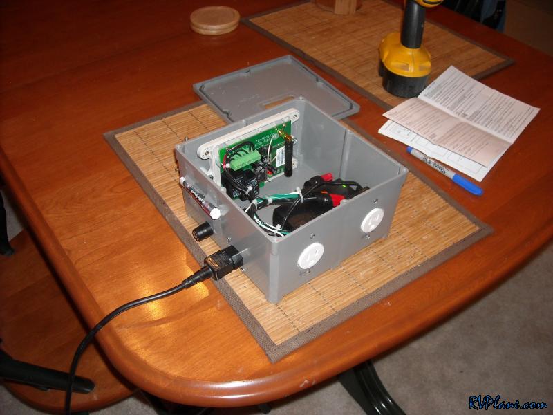
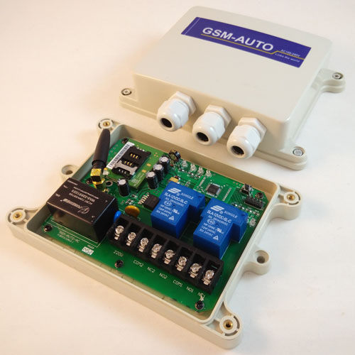
This is the assembled kit, which I screwed to the bottom of the box with 4 screws in the corners of the board.

Closer view of the board. Ignore the orange piece of tape - it shouldn't be there. Large blue box is the relay - rated at 15 A 110 V so should handle most any engine pan heater and/or cylinder heaters (my setup totals 500 W). 110V wires are connected to the common and NO (normally open) points. Red thing is the potentiometer to adjust the sensitivity of the photocell. Photocell is the little thing sticking up from LDR1. It can be bent to whatever orientation is necessary. DC power for the board is on the right (SK2) - I used an old power supply from a telephone or something, but make sure it is 12V and not something else. The board comes with a plug for the "standard" 12V circular plug, but I wired mine direct because of space considerations. Everything else is just put on the board per the instructions in the kit.

This is the same view with a small shelf I manufactured out of scrap Al (lots of that left around the shop!). The photocell is in the center below the hole. I will just put my cell phone on the shelf and hold it down with a couple rubber bands. The key is to make sure you get a phone that lights up CONTINUOUSLY when you call it, and place the screen so it faces the photocell. Adjust the sensitivity so the light from the cellphone triggers the relay consistently. Mine is set to high sensitivity because there is no other light that can enter the box so I am not worried about extraneous triggers. By the way, there are two modes on the circuit board. Mode one is where a single call switches the relay on for a preset amount of time up to an hour. Mode two requires two calls (in close succession) to the phone to switch it on, and it stays on until a third call is made, which switches it off. The small USB-style plug in this photo is cell phone power.
Other notes. I just took some RTV and glued the two transformers (one for the circuit board, second for the cell phone) into the corners of the box. I soldered pigtails onto the plugs for these transformers to make them easy to wire (see figure 2 above). For the power cords, I just cut an old extension cord in half.
All in all, a pretty easy and cheap way to remotely turn on my heater! The only drawback is the cell minutes. Since I never answer the phone, I don't use any minutes, but they expire after a certain time, so I'll have to get more minutes next winter. I am hoping I can find a better/cheaper deal on minutes than the $20 cards that I see.
If anyone needs more details, feel free to PM me (I will be out of town all next week, however).
cheers,
greg
A couple weeks ago I posted a request here regarding build-your-own remote cellphone-operated switch to turn on my engine heaters remotely. I finished putting this together tonight. Total cost about $50 as follows:
$11 - 4 x 6 x 6 plastic junction box from Home Depot (includes a sealable waterproof lid!)
$18 - Apogee kit (http://www.apogeekits.com/remote_control_via_cell_phone.htm) including shipping
$10 - cheap walmart cellphone, comes with 10 minutes (good for 30 days)
$20 - optional additional minutes, good for 90 days

This photo shows the wiring inlet - standard electrical fixture (I got a waterproof one, but unless this is outside, waterproof is probably not necessary)

This is the assembled kit, which I screwed to the bottom of the box with 4 screws in the corners of the board.

Closer view of the board. Ignore the orange piece of tape - it shouldn't be there. Large blue box is the relay - rated at 15 A 110 V so should handle most any engine pan heater and/or cylinder heaters (my setup totals 500 W). 110V wires are connected to the common and NO (normally open) points. Red thing is the potentiometer to adjust the sensitivity of the photocell. Photocell is the little thing sticking up from LDR1. It can be bent to whatever orientation is necessary. DC power for the board is on the right (SK2) - I used an old power supply from a telephone or something, but make sure it is 12V and not something else. The board comes with a plug for the "standard" 12V circular plug, but I wired mine direct because of space considerations. Everything else is just put on the board per the instructions in the kit.

This is the same view with a small shelf I manufactured out of scrap Al (lots of that left around the shop!). The photocell is in the center below the hole. I will just put my cell phone on the shelf and hold it down with a couple rubber bands. The key is to make sure you get a phone that lights up CONTINUOUSLY when you call it, and place the screen so it faces the photocell. Adjust the sensitivity so the light from the cellphone triggers the relay consistently. Mine is set to high sensitivity because there is no other light that can enter the box so I am not worried about extraneous triggers. By the way, there are two modes on the circuit board. Mode one is where a single call switches the relay on for a preset amount of time up to an hour. Mode two requires two calls (in close succession) to the phone to switch it on, and it stays on until a third call is made, which switches it off. The small USB-style plug in this photo is cell phone power.
Other notes. I just took some RTV and glued the two transformers (one for the circuit board, second for the cell phone) into the corners of the box. I soldered pigtails onto the plugs for these transformers to make them easy to wire (see figure 2 above). For the power cords, I just cut an old extension cord in half.
All in all, a pretty easy and cheap way to remotely turn on my heater! The only drawback is the cell minutes. Since I never answer the phone, I don't use any minutes, but they expire after a certain time, so I'll have to get more minutes next winter. I am hoping I can find a better/cheaper deal on minutes than the $20 cards that I see.
If anyone needs more details, feel free to PM me (I will be out of town all next week, however).
cheers,
greg
Last edited:
 )
)