Having been involved with at least three prior Vans Aircraft engine installations, with fellow EAA members, I’ve had some time to mull over the best way to install an engine into my RV-7.
In the prior efforts I was involved in, the basic ingredients were there. We had an engine hoist, and “Bullets” that the AN7 bolts chased. We had 4-5 able former Air Force Pilots and Engineers to do the job. Installing the bolts should be a fairly painless process, right? And it should get easier when our group did it by the third time, right? Wrong and wrong. By the third installation, it still took 3 hours to install, and some serious pushing on the engine dangling from the hoist. On top of that, I wasn’t too excited about the potential for linear scratches in the engine mount bolt holes. I figured the mount is probably A356 cast aluminum, or equivalent, and why scar it up? Beating the bolts into submission caused me to think maybe the process could be improved on. In the end, I was able to install my engine in 50 minutes, by myself. Rounded to one hour, this was one man-hour vs. 15 or so man hours I have been a part of.
There were two main problems I saw with previous installation attempts:
1. An engine hoist can do the heavy lifting needed for a 300+ lb engine (I have a Barrett O-360), but another way to simultaneously “coax” the engine is needed. Having grown men grunt and groan to to sustain a push on the engine didn’t seem to work too well.
2. The “Bullet” we used before was slightly cupped at the aft blunt end to try to capture the front end of the AN7 bolt. It didn’t work well, since the bolt is not properly prepared to receive the bullet. The tip of the bolt, unmodified, is not very flat and didn’t seem to nest well in the bullet. As soon as the bullet/bolt combination split plane saw the engine mount/isolation mount split plane the bullet/bolt would shift radially. The bolt would then no longer be aligned with the mount hole (and bullet in it). All the thrashing away with a hammer would not easily persuade the bolt to enter the mount hole. And again if it did, there could be some scarring action going on. Cracks like initiation sites, such as scratches.
The solution (link to full document with images below):
http://numatx-tools.com/doc/ENGINE-BOLT-MOD.pdf
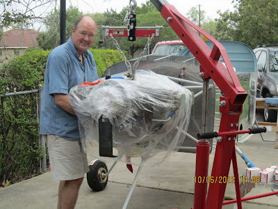
#1. This is in the form of a floor jack and 2x4. This allows the engine to nudged, lifted subtly, or rotated about the hoist point (roughly the cg but not exact). You may need to force the engine up and aft or up and fwd, and the jack allows you to do this by proper placement of the 2x4. Figure 1 shows my installation setup. I have the luxury of an overhead crane, but an engine hoist should be equivalent. The longer the chain can be made suspending the engine the more swing compliance you will have.
#2. The front end of the bolt needs to have a step which will plug into the aft end of the bullet. The bullet and bolt dimensions are shown in Figure 2 The purpose is to prevent the bullet/bolt combination from shearing (shifting) right at the point when the combination sees the split plane. The bolts can be modified on a manual lathe. You want to only cut in a radial direction with a square cutter, so as not to push the threads over. The unmodified bolts don’t begin to have a flat on their ends, and so a facing operation of about .030” on a lathe is needed for a nice bullet interface. The tip of the bolt can be touched up with paint, to address any corrosion concerns. Obviously there can be some adjustments made to these dimensions, but the key point it to have a gap between the bolt step and bullet ends, to prevent damaging the bolt threads if any slight tapping is required during the chase operation (Figure 3).
Hope this may be helpful during your installation.
Mark Swinford
Numatx, Inc.
P.S. - This is NOT a shameless plug for my website. I am currently very busy dealing with Boeing and other commercial users of my rivet squeezers. If I could have attached this PDF file directly to this thread I would have.
In the prior efforts I was involved in, the basic ingredients were there. We had an engine hoist, and “Bullets” that the AN7 bolts chased. We had 4-5 able former Air Force Pilots and Engineers to do the job. Installing the bolts should be a fairly painless process, right? And it should get easier when our group did it by the third time, right? Wrong and wrong. By the third installation, it still took 3 hours to install, and some serious pushing on the engine dangling from the hoist. On top of that, I wasn’t too excited about the potential for linear scratches in the engine mount bolt holes. I figured the mount is probably A356 cast aluminum, or equivalent, and why scar it up? Beating the bolts into submission caused me to think maybe the process could be improved on. In the end, I was able to install my engine in 50 minutes, by myself. Rounded to one hour, this was one man-hour vs. 15 or so man hours I have been a part of.
There were two main problems I saw with previous installation attempts:
1. An engine hoist can do the heavy lifting needed for a 300+ lb engine (I have a Barrett O-360), but another way to simultaneously “coax” the engine is needed. Having grown men grunt and groan to to sustain a push on the engine didn’t seem to work too well.
2. The “Bullet” we used before was slightly cupped at the aft blunt end to try to capture the front end of the AN7 bolt. It didn’t work well, since the bolt is not properly prepared to receive the bullet. The tip of the bolt, unmodified, is not very flat and didn’t seem to nest well in the bullet. As soon as the bullet/bolt combination split plane saw the engine mount/isolation mount split plane the bullet/bolt would shift radially. The bolt would then no longer be aligned with the mount hole (and bullet in it). All the thrashing away with a hammer would not easily persuade the bolt to enter the mount hole. And again if it did, there could be some scarring action going on. Cracks like initiation sites, such as scratches.
The solution (link to full document with images below):
http://numatx-tools.com/doc/ENGINE-BOLT-MOD.pdf
#1. This is in the form of a floor jack and 2x4. This allows the engine to nudged, lifted subtly, or rotated about the hoist point (roughly the cg but not exact). You may need to force the engine up and aft or up and fwd, and the jack allows you to do this by proper placement of the 2x4. Figure 1 shows my installation setup. I have the luxury of an overhead crane, but an engine hoist should be equivalent. The longer the chain can be made suspending the engine the more swing compliance you will have.
#2. The front end of the bolt needs to have a step which will plug into the aft end of the bullet. The bullet and bolt dimensions are shown in Figure 2 The purpose is to prevent the bullet/bolt combination from shearing (shifting) right at the point when the combination sees the split plane. The bolts can be modified on a manual lathe. You want to only cut in a radial direction with a square cutter, so as not to push the threads over. The unmodified bolts don’t begin to have a flat on their ends, and so a facing operation of about .030” on a lathe is needed for a nice bullet interface. The tip of the bolt can be touched up with paint, to address any corrosion concerns. Obviously there can be some adjustments made to these dimensions, but the key point it to have a gap between the bolt step and bullet ends, to prevent damaging the bolt threads if any slight tapping is required during the chase operation (Figure 3).
Hope this may be helpful during your installation.
Mark Swinford
Numatx, Inc.
P.S. - This is NOT a shameless plug for my website. I am currently very busy dealing with Boeing and other commercial users of my rivet squeezers. If I could have attached this PDF file directly to this thread I would have.
Last edited:
 For my 540, I did the install by myself in less than 30 minutes with just my Habor Freight engine crane and the hardward that came with the kit.