Van's Air Force

The definitive Van's Aircraft support community! Buying, building or flying an RV? Join our exclusive family of mentors and enthusiasts!

Bob archer antenna

Gator & Pilot 8

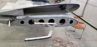
Here's mine a few years ago while under construction. The red tape held the antenna in place while under construction and was replaced with a layer of 5 oz. fiberglass a few days after this photo was taken. Aeroled strobe/nav ligt was used just forward of the antenna under the wingtip lens. Note the antenna is not flush with the edge of the wingtip.

Have 150 hours on the plane now and the antenna works as well as any I've used in other aircraft.


Archer RightTip.jpg
 
Last edited:
OK scratch that last,,biax cloth
Nutplates are riveted to the wintip with the antenna sandwiched between the wingtip and and the nutplates. Screws hold the wingtip to the wing skin. The onboard wing rib flange faces inboard. 😀
ok theres my disconnect. I was asking about mounting my antenna on a piece of angle to the outboard rib versus on the wing tip mounting screw nut plates or in my case piano hinge. I was just wondering how those who mount it on the outboard rib keep that flimsy antenna from flopping all over the place in the wing tip. Think I’m going to go back to mounting it on the wing tip mounting hinge,
 
I have made the Archer antenna for most of my RV builds. In my experience, they perform acceptably as a NAV antenna when navigating with VORs. Where they shine IMHO is as a LOC/GS antenna. Rock solid. I am sure that has something to do with being close to the station and the airplane pointing directly at the transmitter. If that's all you use it for, it can't be beat.

One of my homemade versions is installed into our East Coast RV-14A, N914VA. Worked great while I had the airplane. Might ask our rep, Zack for his experience.
My experience also no issues with ILS approaches or Nav with the Dynon D-100 or a Vor KI108 indicator
 
I like this mounting method, but just got my Bob Archer antenna in today, had no idea they were so flimsy. Mounted like this, how do you keep the antenna from flopping around all over the place?
To start, I don’t use the Bob Archer antenna. I make my own. Follow the instructions in the AeroElectric bible but change the dimensions to take full advantage of whatever wingtip width you have. The more of the antenna extending outboard of the last wing rib the better to enhance antenna range. I typically get VOR well past 100nmi and LOC/GS beyond practical range. You will need to borrow and antenna analizer to get the now modified antenna lengths correct. Borrow one and while you have it ring out your comm antennas and feed line to make sure all is good.

Using the same photo, you can see the black split conduit attached to the outside eleement. That conduit rides in the wingtip far inside edge. It does not flop around.

Also note the antenna is mounted more aft of the leading edge than shown in the Archer instructions. This moves it way from potential RFI created by the nav & strobe LEDs. No reason to cram it forward at all - and do not run lighting wires along the antenna element.

Carl
 

Attachments

  • 20200403_135130.jpeg
    20200403_135130.jpeg
    1.6 MB · Views: 71
To start, I don’t use the Bob Archer antenna. I make my own. Follow the instructions in the AeroElectric bible but change the dimensions to take full advantage of whatever wingtip width you have. The more of the antenna extending outboard of the last wing rib the better to enhance antenna range. I typically get VOR well past 100nmi and LOC/GS beyond practical range. You will need to borrow and antenna analizer to get the now modified antenna lengths correct. Borrow one and while you have it ring out your comm antennas and feed line to make sure all is good.

Using the same photo, you can see the black split conduit attached to the outside eleement. That conduit rides in the wingtip far inside edge. It does not flop around.

Also note the antenna is mounted more aft of the leading edge than shown in the Archer instructions. This moves it way from potential RFI created by the nav & strobe LEDs. No reason to cram it forward at all - and do not run lighting wires along the antenna element.

Carl
Hey Carl, yeah I saw your post about your homemade antenna (1st first rate input as always) after I had already bought the archer so think I’ll go ahead and go with it. And no I hadn’t noticed that cinduit you used to stabilize the assembly. I’ll give that some thought, thanks again
 
The antenna is a funky beast- the coax center conductor connects to a 4" piece that is capacitively coupled to the inboard and outboard sections. Both inboard and outboard sections are directly connected to the wing skin, so at DC it's a short, however at antenna frequencies they become inductors. That 4" section ends up looking like a 1/4 wave antenna. There is some crazy reception lobe shaping going on with the outboard L shaped section. All this made me realize following the directions might be a safe way to go.
Thanks and agreed yeah the antenna is a funky beast. I know too much research can be detrimental sometimes but I kept reading about potential loss of conductance through the wing tip piano hinge over time. I can maybe see that but I’m doubting it would become an issue. Just for the hell of it and as added insurance I’m going to run a ground wire from the antenna ground leg to a nutplate on the outward rib.
 
….Just for the hell of it and as added insurance I’m going to run a ground wire from the antenna ground leg to a nutplate on the outward rib.
Remember you’re dealing with RF at 115 MHz. Any such wire should be very short. Remember that there is no requirement that the ‘ground leg’ be at the same potential as the aircraft ground. Just that there is a large conducting surface perpendicular to the antenna and connected to the coax braid.
While the Archer ‘looks funky’, if you rotate it 90 deg around the ground leg, it looks a lot like the common bent whip used on the belly for com frequencies. And while the feed arrangement is uncommon on aircraft, it is very common on amateur radio antennas used around 20 meter wavelengths. Edit. If anyone has an older Cessna with a bottom mounted marker beacon antenna, it used the same ‘gamma match’ feed line attachment method.
 
Last edited:
Remember you’re dealing with RF at 115 MHz. Any such wire should be very short. Remember that there is no requirement that the ‘ground leg’ be at the same potential as the aircraft ground. Just that there is a large conducting surface perpendicular to the antenna and connected to the coax braid.
While the Archer ‘looks funky’, if you rotate it 90 deg around the ground leg, it looks a lot like the common bent whip used on the belly for com frequencies. And while the feed arrangement is uncommon on aircraft, it is very common on amateur radio antennas used around 20 meter wavelengths.
I have an VOR Archer in my wingtip. I am going to be running wires shortly. I have wingtips installed with hinge pins and planned on the dedicated wire to ground to the last rib.

You obviously have more info than I do. What do you recommend?
 

I have an VOR Archer in my wingtip. I am going to be running wires shortly. I have wingtips installed with hinge pins and planned on the dedicated wire to ground to the last rib.

You obviously have more info than I do. What do you recommend?
I actually recommend Carl’s attachment method (post #54). It solves the ‘good ground plane connection’ problem, and also makes tip removal much easier. Glue some foam blocks in the tip to support the antenna part. Edit: any ground wire won’t be short because it will need enough slack to allow you to remove the tip. A long ground wire may cause more problems than it fixes.
 
Last edited:
Remember you’re dealing with RF at 115 MHz. Any such wire should be very short. Remember that there is no requirement that the ‘ground leg’ be at the same potential as the aircraft ground. Just that there is a large conducting surface perpendicular to the antenna and connected to the coax braid.
While the Archer ‘looks funky’, if you rotate it 90 deg around the ground leg, it looks a lot like the common bent whip used on the belly for com frequencies. And while the feed arrangement is uncommon on aircraft, it is very common on amateur radio antennas used around 20 meter wavelengths.
I have an VOR Archer in my wingtip. I am going to be running wires shortly. I have wingtips installed with hinge pins and planned on the dedicated wire to ground to the last rib.

You obviously have more info than I do. What do you recommend?
 
I actually recommend Carl’s attachment method (post #54). It solves the ‘good ground plane connection’ problem, and also makes tip removal much easier. Glue some foam blocks in the tip to support the antenna part. Edit: any ground wire won’t be short because it will need enough slack to allow you to remove the tip. A long ground wire may cause more problems than it fixes.
Not an option. I purchased the Archer and its installed in the wingtip. My question was what do you like for the grounding of the antennae?

Edit: I didn’t get the previous post till after.

My Archer is firmly attached to the hinge pin
 
Try it the way it is- the hinge may provide a good ground. Do you have access to something to measure the VSWR such as a NanoVNA?
My aircraft is currently at the avionics shop. I got it painted and they are doing the full IFR upgrade. I will check with them.
 
Aircraft Spruce Archer specs: "The VSWR is normally less than 2.0:1 over a frequency band of 108 to 127 Mhz but could be higher due to installation factors."
I was measuring the VOR band VSWR of less than 3.0 measured at the radio end of the coax. A VSWR of 2 is 11% of the power is reflected back; a VSWR of 3.0 is 25% of the power is reflected back. If you are interested, I can dig up the plots measured for both VOR and GS bands.
I am an A&P and definitely NOT an avionics guy. I’ll let my avionics guy sort it out.
 
Back
Top