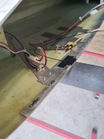
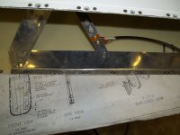
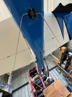
hard to tell from your photo of the tip detached, but those power lines to the lights/strobes don’t appear to be IAW archers install instructions which are explicit about routing up the forward element. Looks like they loop around over the top of the element then back outboard.
I will review this and improve. However, the situation has been unchanged from day 1 and did not seem to cause any issues.
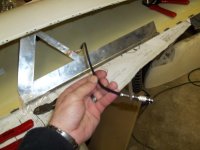
The only recent change (after starting to trouble shoot the GS issue) is the addition of the black grounding strap that improves the ground connection to the wing. Previously that was only established through the nutplates and screws to wing skin contact.
Let me see. SL30, GS always worked. Removed SL30, installed Trig. Unplugged nav coax (one cable), plugged into Trig. Now Trig GS is crap. Did you do anything to the antenna? What makes you think that’s the problem? Installed new ground connection (Is that the black wire that loops out across the antenna, then back to a rib? This is RF, wire lengths matter. This should be as short as possible.) You say the new wire greatly improves nav audio. But that’s the same signal that drives the vor cdi, which you said was already great. There’s something very strange going on here. Return antenna to previous condition (make sure there’s no paint/corrosion under the tip attach screws), re-assemble, get a third loaner from Trig, make sure Archer coax is plugged all the way in, try again.
Practically all correct.
- Only change at the time of the swap was the SL30 Cradle Coax Plugs/Ends on the Nav and Com RG400's were changed by a certified Avionics Technician to Standard BNC plugs, which now attach to the Trig cradle.
- No change was done to the antenna itself.
- Then did several test flights and found the only problem to be the GS reception. (And Nav Audio was rather weak in volume, but still easily detectable)
- CDI/VOR display always worked fine, did not test to max range, but in the order of 50NM from VOR / 18NM from ILS did definitely work. However, GS only at 5-6NM.
- This, irrespective of orientation towards the emitter (thought maybe the fuselage could be shading the wingtip affecting signal strength or so, never was a problem with the SL30 however). No matter whether intercepting from left or right - same result.
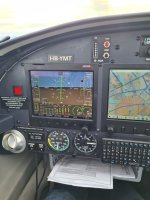
- First suspected a serial protocol / display issue between the TX56 and the EFIS as during the first test flight, I never got close enough to the GP, so never received a signal. As I only tested at intercept altitudes / FAF, cruising around waiting for the GS to appear on at least two different ILS's...
- On further flights, once i started visual descents and got close enough to the GP, I did receive the signal and the display on the EFIS became alive and correct. Hence any serial protocol issue appears very unlikely.
- No diplexers or any other kind of active/passive special hardware in the coax path.
- In discussions with Trig we concluded (and the weak Nav Audio hinted to) some kind of Antenna issue / compatibility with the Archer antenna.
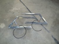
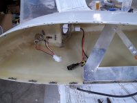
- I first wanted to try to improve the grounding, knowing this was somewhat sketchy from the start. The antenna ground leg, metal strip that holds the nutplates and nutplates themselves are all on the inside of the fiberglass wingtip and the connection ot the airframe was mainly established via the screws/nutplates (and the screws over the painted skins, i think i intentionally removed the paint on one of the screw holes!). Yet it worked for all these years, however it could have corroded.
- So decided to add a dedicated grounding strap, connecting the ground side of the wingtip antenna with the outboard wing rib. This did improve the strength of the Nav Audio return (at least I believe it is more than expectation bias *G*).
- The fact that the archer antenna works for most here in the forum, has worked for me in the past and even now works fine for the Localizer & VOR via the exact same cable/installation/plugs, yet not for the GS is extremely puzzling (and on 2 separate TX56 devices, too).
- I doubt that e.g. the new BNC plugs could somehow be "leaking" the 300ish MHz Band while at the same time working perfectly in the 110 range...


.jpg")