Van's Air Force

The definitive Van's Aircraft support community! Buying, building or flying an RV? Join our exclusive family of mentors and enthusiasts!

Artex 345+Remote Pinouts?

Tall_Order

Well Known Member
Patron
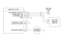
I am finding the documentation for wiring the Artex 345 to the remote convoluted as I can’t find any info on the remote head’s pin outs(9 pin molex). As this is a popular ELT, I am hoping there are some forum members with some insight into the number of wires between the remote and the unit itself. Is it really only 2? Also I am thinking it is a safe bet that I will have to run a wire(s) to more than 2 of the 9 molex pins on the remote switch…

Any help appreciated.

(Don't have these items yet but roughing in the wires and can't figure out conclusively how many wires it is)

 
Thanks, I was looking at that image and thinking that the remote switch probably requires at least a ground wire unless pins 3 and 14 are data wires which I think is unlikely. (The remote unit is both a switch and a lamp, but only 2 wires)

I was hoping there is some info on that 9 pin Molex (unidentified pinouts other than the 2 above) on page 47 of the manual?
 
From the pg 48 of the manual...
Cockpit Remote Switch 9-Pin Plug Installation

1) Insert the wiring pins into the Molex 9-pin cockpit remote switch plug. Refer to Figure 17 Typical 2-Wire Installation for Unshielded Harness on page 44, Figure 18 Typical 2-Wire Installation for Shielded Harness on page 45.
 
Thanks, I was looking at that image and thinking that the remote switch probably requires at least a ground wire unless pins 3 and 14 are data wires which I think is unlikely. (The remote unit is both a switch and a lamp, but only 2 wires)

I was hoping there is some info on that 9 pin Molex (unidentified pinouts other than the 2 above) on page 47 of the manual?
You're overthinking this. It's just two wires. Wire it like the schematic shows. If you wire it correctly the lamp will work. If you cross the wires it won't.
 
The diagram implies the use of a 3 wired shielded connection. The 2 wires go to the switch while 1 wire goes to your GPS. I thought it worked better to use a shielded pair for the switch and a shielded single wire to the GPS. Some might say shielding is not needed, but better to be safe than sorry and this follows the MFG guidance. Shielded are tied as shown in the diagram.
 
Thanks @kirkbauer for the full schematic. I saw a couple VAF threads mentioning the need to have a magic box on ELT pin 9 (to change protocol and baud rates) but nice to see that it may not be necessary if sourcing off an IFR Navigator. ( I am planning on using one of the many RS-232 GPS OUTs on my GPS400)

Also I was highly suspicious that I was missing something when there is a 9 pin Molex with only 2 of them used so thanks everyone for confirming. Ordered the correct number of conductor wire and will rough in accordingly (y)
 
Back
Top