What's new
Van's Air Force

Don't miss anything! Register now for full access to the definitive RV support community.

Another Super 8 was "Born" today

BlackhawkSP

Well Known Member
I helped a Buddy calibrate the Garmin G3X Touch fuel sending units today. This thing is going to be a Beast. The IO-540 has 9.5 to 1 pistons, cold air induction, one mag, and 1 LSE for ignition. The wings are also clipped shorter by one bay.


I'm betting it'll do 195 KTS true all day long. As you can see from the picture, it has the Show Planes cowl, flip over canopy, and the turtle back modification. He should get the paperwork finished tomorrow, and then on to flight testing.
 

Attachments

  • N320XP.jpg
    N320XP.jpg
    428 KB · Views: 505
Last edited:
Awesome! What else was done in conjunction with the 6 cylinder engine? The tail looks like a stock -8 tail or is it F1? What about thicker fuselage skins? You mention shorter wings by one bay.. are the ribs spaced tighter or does it have original rib spacing? Stock fuel tanks? What does it weigh empty?
 
Other changes

We used one piece skins on the trailing edge of the wings, .032 thickness, added tip tanks which hold 12 gallons each. The canopy, fuselage top and engine cowling are Showplanes, and his kit is fabulous. Also have aluminum gear legs and MT propeller. It has 3 axis auto pilot as well. Should be able to cruise close to 1,000 miles. Empty weight about 1,250 lbs.
Larry Boggs
Civilian pilot
 
Awesome! What else was done in conjunction with the 6 cylinder engine? The tail looks like a stock -8 tail or is it F1? What about thicker fuselage skins? You mention shorter wings by one bay.. are the ribs spaced tighter or does it have original rib spacing? Stock fuel tanks? What does it weigh empty?

It's the original rib spacing, but one bay shorter. It should have a very high roll rate, for sure. The tail feathers are stock RV-8.
 
Last edited:
My concern is more the wing. 70# weights on the tips like to amplify any structural divergence. Your wing is shorter but not appreciably stiffer.

My commendations on your build. Wring it out carefully in the flight testing and respect the established limits.

Congrats. Stay safe
 
What engine mount?

Did you use a special engine mount to get the engine closer to the firewall for W&B purposes and to make it so you could use the Showplanes cowling? I’d sure like to see some pictures of it with the cowling off.
 
Last edited:
Did you use a special engine mount to get the engine closer to the firewall for W&B purposes and to make it so you could use the Showplanes cowling? I’d sure like to see some pictures of it with the cowling off.

The beefy mount was built by the late great John Marshall. It's the same mount that most all Super 8's have. It puts the engine 4 inches closer to the firewall for W&B purposes. The owner said he will add more pictures soon.
 
wing load

With the short wings, the one piece .032 trailing edge on the wings, should gain some strength, but the tip tanks will only be used for long cross country's, not everyday flight. Caution is the key.
 
With the short wings, the one piece .032 trailing edge on the wings, should gain some strength, but the tip tanks will only be used for long cross country's, not everyday flight. Caution is the key.

Not trying to be a pain or dampen the build accomplishment. There is good reason for associated pride and sense of accomplishment.

I'm not talking about the wing's ultimate strength but rather the aeroelastic flutter. I have no idea how much design margin remains in this regard. I can reasonably assure you that part of that margin has been used in the new configuration. As mentioned, the wing is not appreciably stiffer. Even if the tip tanks are only utilized in cruise type missions, the concern remains. If any turbulence is encountered, I'd be quick to throttle back. Maybe some of the smart guys here will read and share their knowledge; Steve @ SCsmith? Dan @ DanH/ Maybe they'll say I'm full of **** and my concerns are overstated. Won't be the first time

I'll say again, wring it out during the flight testing; all the configurations/corners or the envelope. Know that you're going in with some unknowns and respect them.

Stay safe.
 
I don't know what the aeronautical engineers here could say that would be helpful... Without knowing what engineering was done to validate these mods there is very little that can be said about them, other than "that's a nice looking plane, let me know when it's been flight tested." All of these mods eat away at the safety margins present in the original design, but could also be completely safe if the changes were properly engineered in advance.

The Rocket design re-spaced the same number of ribs in the stock wing closer together when the wing was shortened, increasing stiffness. As mentioned, tip tanks change the aeroelasticity of the wing... additional stiffness would seem to be a good thing to have.

"Could cruise at 195kt all day..." Great, but isn't that over Vne?

Fly safe...
 
The aircraft should actually do a bit better than 195 knots. Our Rocket with the exact same engine setup cruises at 210 to 214 kts in the 9500 to 11500 range. That is however at 14 GPH ROP. We normally run at 11.5 GPH LOP and see about 195.
 
I don't know what the aeronautical engineers here could say that would be helpful... Without knowing what engineering was done to validate these mods.... .

To the point; will adding weight to the tips exacerbate aeroelastic flutter? Nothing in my reasoning or related technical experience says it won't. I was wondering if someone skilled or experienced in such art feels the same.

This isn't saying the builder's approach isn't unsafe. It is a presumed unknown (to me at this moment). This may be a duplicate of someone else's approach that has been operationally validated. I wish everyone involved a whole lot of safe flying hours.
 
The effect of tip tanks on flutter margins

To the point; will adding weight to the tips exacerbate aeroelastic flutter?

The effect of tip tanks on flutter margins, all other things being unchanged. Some comments in very general terms regarding basic wing bending/torsion flutter:

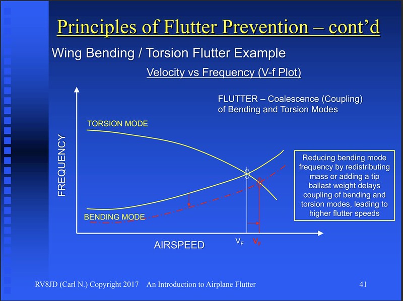
1) The weight of the tip tank and fuel reduces the frequency of the first wing bending mode. This further separates the first wing bending mode frequency from the first wing torsion mode frequency and delays coupling (coalescing) of these two modes (i.e., where their frequencies approach one another). This will increase the flutter speed (hence increases flutter margin). This is frequency decoupling of the wing bending/torsion modes. (Yes, the torsion frequency of the wing decreases due to the increased pitch inertia of the tip tank and fuel, but the reduction in wing bending frequency is a much larger player compared to that effect. But both effects need to be considered.)

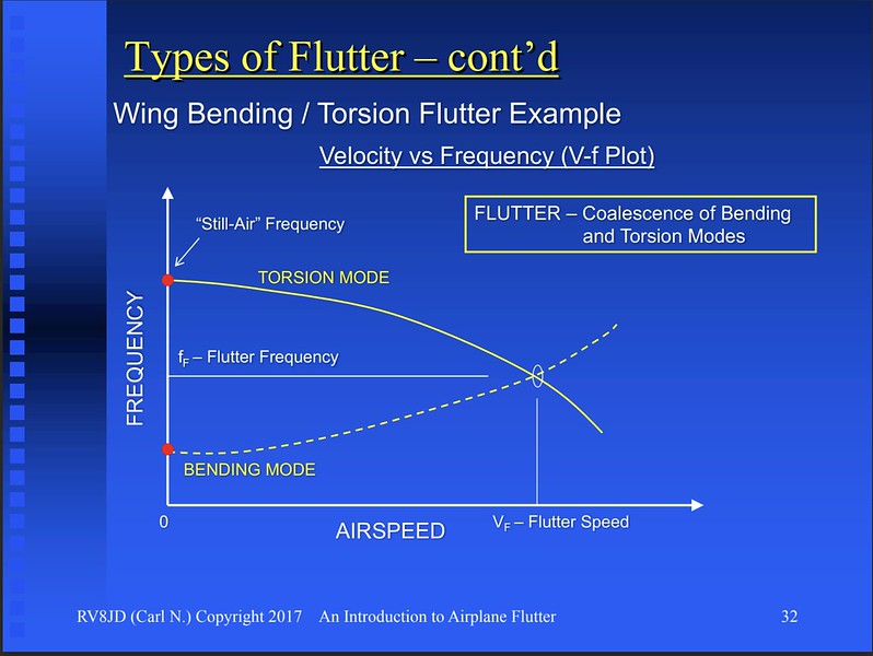
Illustrating what was said above. Without tip tank:

i-PDRCwGR-L.jpg

With tip tank:

i-X3d73NC-L.jpg


2) However, the cg of the tip tank and fuel is very important. If the fore-aft cg of the tip tank and fuel is forward of the elastic axis of the wing, the flutter speed will increase. This is modal decoupling of the wing bending/torsion modes. If the cg of the tip tank and fuel is aft of the elastic axis of the wing, the flutter speed will decrease (hence decreases flutter margin).

The vertical cg of the tip tank with fuel is also important. The further the cg is above or below the wing chord plane, the worse the flutter characteristics will be since the frequency of the wing's torsion mode will decrease. Since this tip tank configuration seems to be within the normal wingtip shape, the vertical cg should be near the wing chord plane, so I won't discuss this effect further.

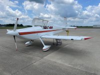
3) The aileron is partially mass balanced, so hopefully wing/aileron flutter will not be an issue. However, since the RV-8 aileron is not 100% statically mass balanced, it is possible that more mass balance may be needed to preclude the aileron rotation mode from coupling with the modified wing modes below 1.20 x Vd (where Vd is equal to 1.10 x Vne).

Ideally, the combination of these effects would need to be assessed by flutter analysis (to 1.20 x Vd), ground vibration testing (to measure the modes and frequencies to compare to the predicted values used in the flutter analysis and adjust if necessary), and then validated by flight testing to Vd.

For those interested in flutter, here is a primer I put together awhile back:

 
Last edited:
For our constant chord, constant thickness wings, the elastic axis is roughly slightly forward of half way between the spars.

Carl, are you sure this is true for RV wings?

The rear spar is only pin-joined to the fuselage so I wouldn't think it contributes much to bending stiffness. On the other hand, the leading edge "D" tube is pretty stiff in bending. So I have always assumed that the elastic axis is pretty close to the main spar. Is that a poor assumption?

Good points Steve. I was just taking a swag to give folks an idea of where the elastic axis might be. You're right, it is further forward than where I guessed. Need a good stress guy to figure out exactly where it is! ;)
 
Last edited:
The effect of tip tanks on flutter margins, all other things being unchanged. Some comments in ……

Carl, are you sure this is true for RV wings?

The rear spar is only ……..

Thanks to you both. It’s interesting, to me at least. Monocoque/semi-mono construction, I would assume, behaves more tube-ish. but it’s obviously too complex for such a simplification. I would guess the pre-CAD guys used such assumptions and let the benefits of other stiffening effects add to design margin.

Let me admit that my initial concerns/questions centered around the (inverse) damping effects of tip weights versus tuning the divergence response. Complex subject matter for sure.

All that said, I’m sticking with my initial concerns.

Side note/drift. You had the X29 in your presentation. The forward swept wing was only a small part of this test program but it was still cool. I got to sit in that machine out at Dryden in my Space shuttle days. Despite being an inherently unstable aircraft, it was very de-tuned early on. “Fighter that fly’s like a bomber” Got to witness the frequency response test after a software mod. Plane moved all over the place. It wasn’t a big aircraft but pretty sexy looking and paved the way for a lot of later FBW aircraft.
 
Monocoque/semi-mono construction, I would assume, behaves more tube-ish. but it’s obviously too complex for such a simplification. I would guess the pre-CAD guys used such assumptions and let the benefits of other stiffening effects add to design margin.

No assumptions necessary since the location of the elastic axis (EA) can be, and was, calculated (even pre-CAD!! Imagine that!!). The stress guys would normally do that for us dynamicists when we were using beam-lumped mass models of the structure. With FEM models, no real need to know where the EA is, except for rough checks of the model, and initial placing of certain items like tip tanks, external stores, etc.

Let me admit that my initial concerns/questions centered around the (inverse) damping effects of tip weights versus tuning the divergence response. Complex subject matter for sure.

Yes, I saw that one of your first posts mentioned (static) divergence and a later post mentioned flutter. Although both are aeroelastic phenomena, they are two different things. My post just covered the flutter aspects.

My guess is that the tip tank fuel will not adversely affect the divergence speed of the wing even if the fuel cg is a little aft. Static divergence is basically a function of torsional stiffness and steady state aerodynamics (as opposed to the unsteady/oscillatory aerodynamics that affect flutter), and not really affected by weight.

Side note/drift. You had the X29 in your presentation. The forward swept wing was only a small part of this test program but it was still cool. I got to sit in that machine out at Dryden in my Space shuttle days. Despite being an inherently unstable aircraft, it was very de-tuned early on. “Fighter that fly’s like a bomber” Got to witness the frequency response test after a software mod. Plane moved all over the place. It wasn’t a big aircraft but pretty sexy looking and paved the way for a lot of later FBW aircraft.

Cool! That page in my presentation covered static divergence. The Fokker D.VIII suffered from static divergence, and the X-29 was prone to static divergence due to its forward swept wing. Of course the FBW control system and the stiff composite wing kept any divergence tendencies at bay. Aft swept wings are not prone to divergence.

i-xJCRgV4-M.jpg
 
Last edited:
….Yes, I saw that one of your first posts mentioned (static) divergence and a later post mentioned flutter. Although both are aeroelastic phenomena, they are two different things. My post just covered the flutter aspects.

Thanks for getting me smarter. Had not thought about any of this in a very long time.

Sorry but another question. I thought the tip divergence was one of the potential forcing functions for aeroelastic flutter? Deflection -> localized increased alpha -> more localized lift -> more deflection -> …. bit of a doom loop.

I would assume the fat RV wings are much less susceptible to the aforementioned than thinner wings of very high performance aircraft.
 
Last edited:
Hmmmm….

Personally, I’d back away from high speeds with the fuel system described. Another set-up would be to use the EVO wing, or something like it where the wing has 3 spars: one near the nose (boxed), main spar, (also boxed), and the aft spar built like a C channel. In fact, the EVO wing was designed for this use. It wouldn’t be too difficult to copy @ 108SF.

I would think the design as used on the Super 8 with LE tanks but no added internal boxed spars would exhibit some vibration. Descent from cruising altitude would be “careful” indeed, and aerobatic flight would be dangerous with fuel added - getting into turbulence while descending could be rather exciting one way or another.:eek:

If desired, a wing could be made to look like the Super 8 wings if you would want to keep the same platform….
 
Please start a flutter thread so it can be found later. It’s great info but let’s not not steal a man’s thunder on a great looking bird.

Perhaps a moderator can split this into 2 threads.
 
All this stuff in very interesting and WELL above my pay grade. However, I thought the primary weak point for the RVs that take excursions well beyond Vne was flutter in the elevators that then proceeds to rip the H stab off the plane.
 
All this stuff in very interesting and WELL above my pay grade. However, I thought the primary weak point for the RVs that take excursions well beyond Vne was flutter in the elevators that then proceeds to rip the H stab off the plane.

YES to the above!! The weak link on the 8 is the tail feathers.........
 
Echoing what someone said in a previous post, thanks for getting me smarter. Had not thought about any of this in a very ..... Ah who am I kidding, I've never thought about this so deep :D but thanks for giving me something more to learn about, always learning is always a good thing !
 
All this stuff in very interesting and WELL above my pay grade. However, I thought the primary weak point for the RVs that take excursions well beyond Vne was flutter in the elevators that then proceeds to rip the H stab off the plane.

It was stated earlier (Post #8) that since this Super 8 has the stock -8 empennage, the normal -8 Vne speed would be observed. The concern is that the rather heavy tip tanks with fuel could reduce the wing's flutter or divergence speeds to below those of the empennage and possibly below the -8's Vne of 200 KTAS/230 MPH TAS.

Another thing to consider is that the -8's Vno speed (168 KIAS/193 MPH IAS) should be reassessed for the modified wing with the tip tanks with fuel. The amount would depend on the effect of gust loads on the shorter wing with the 0.032" aft skins and the tip tanks with fuel. Maybe that's already been done.
 
Last edited:
FYI. I edited Post #21 to add comments about the vertical cg of the fuel tank w/fuel and aileron mass balance.
 
Elastic Axis

Carl & Steve--Great discussion.

A first cut on the elastic axis could be determined with a simple shear flow analysis. A 4 beam, 2 cell model would be an adequate first cut at the root chord. The shear center (as a percentage of chord) is probably dominated by the main and rear spar caps, and their respective second moments.

At the tip chord a one cell model would be a first cut, with the second moments determined largely by the skin. The shear center of the tip chord can then be determined.

A line drawn between the two shear centers yields a first cut of the elastic axis to give a rough idea of the elastic axis placement relative to the main and rear spars, and the respective cg of the chord. But it is important to then check several other locations along the span in a similar fashion to see if the axis is truly a constant percentage of chord across the span. If it isn't the subsequent flutter calcs become even more challenging.

We've had good luck correlating this type of old school analysis with FEA, with the added benefit that a shear flow analysis across the chord can be used for fastener analysis. The distance between the shear center and the
center of pressure is directly related to the torsion the wing sees at a given aerodynamic load.

It is possible under certain loading conditions that the tensile loads are much larger than one would expect. Since most rivets are designed for shear applications, overlooking tensile loads can be easy to do when a lot of design changes are being juggled as in this wing.

Carl, one other thing--your presentation is outstanding, and I hope everyone flying an RV take a careful look at it. You point out something that I think needs to be highlighted--ad hoc changes to structure to "beef up" structures can have unintended consequences. And one possible consequence is that flutter margin can be reduced.

Well done.
 
Back
Top